A recent simple battery change operation of a small multimeter (DT-182 or a clone of thereo) turned into a disassembly, when I heard a little rattling noise when shaken after I put in the new battery. I was curious if there was anything loose inside the box. Took some pictures of the inside of the multimeter, and added some notes to how things seem to work. I try to guess the origin of the design choices within hardware, in a way to learn a bit about hardware manufacturing.
Disassembled
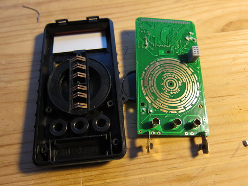
The first thing I did is unscrew the PCB and see whether anything is between that and the front of the housing.
Multimeter: board out
The things I noted here: the knob, the screw hole placement, and the LCD-PCB interface.
Now I understand a bit better how the knob works: the little metal brushes make contacts differently for different position of the knob, and the control electronics knows the required functionality based on reading those connections (specific shorts? specific resistances? that I forgot to check). The brushes are weird a bit too: one fell off and I tried to put pack but didn’t see how it could be attached. Turns out, that the slit in the middle is a bit narrower than a plastic edge underneath, and the brush sticks on to that (barely). When pressing agains the board, the triangle shape can flatten, and keep physical contact. There’s also a whole for the knob centre that is not screwed, but keeps the knob from wandering
The screw hole placement for the PCB is in a triangle shape around he knob. I think it’s a good way to keep things tight with the smallest number of screws.
The LCD interfacing is pretty weird. The display segments of the LCD are controlled through the big bunch of lines on the top of the board. That is touching a rubbery contact stack on the top of the LCD. I guess it’s rubbery because it needs to be able to compress easily. I wonder what’s the conductive material within that . There’s also a plastic bar that the PCB pushes down and which in turn pushes the display down, i.e. into its place of the exposure. I think it’s a quite cool way for easy assembly but holding things quite securely in place. The PCB slips into some slot on the top the enclosure, and pushed into place on the bottom (the metal tubes go into the plastic holes, and the electrodes into their respective slits).
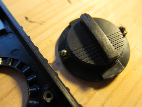
Multimeter: the knob
Taking the knob off, it’s held in place by the balance of the PCB pushing down on its back, and a pair of ball bearings. There’s a spring under each of the bearings, which is within a plastic hole, while the ball is a bit larger than the whole, so it cannot be stuck inside of it. The positions of the knob are set by the holes in the plastic ring (on the left of the image. The balls are greased somewhat, quite sticky. Putting things back together was a bit tricky, not letting the balls fall out on one side, and the brushes to fall off on the other.
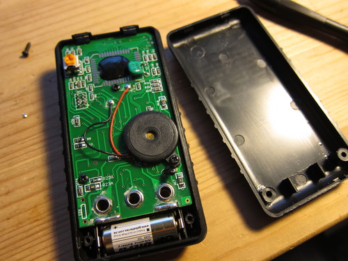
Multimeter: board back
The PCB is secured to the front assembly with three screws. One of them also holds a buzzer in place and that screw is a bit longer – thus not all screws are the same in this gadget.
The backplane has a pair little grooves on the top which fit into the two hinges on the top of the frontplane (I really wonder what’s the proper name for those parts…). Other than that, two screws on the bottom secure the back. The battery is held in place with two plastic legs (between the screws of the backplane).
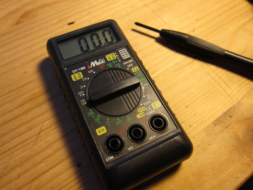
Back in working order
After the second try, I could put everything back and the multimeter seems to work.
Funny thing, when I shake it I can still hear the rattling noise. Now that I’ve seen the inside, looks like it’s the plastic piece that should help to hold the LCD down, so probably it’s smaller than in the other multimeters like this we have, or the PCB is not fastened as much as it is supposed to. Though I don’t like over-fastening metal screws in plastic threads – recipe for shredded threads.
Since my last exploration of bitcoin, there are a lot of things happening in that topic, and the geekiness of it (among other things) didn’t let me go. There were a lot of talks about one more more Bitcoin ATMs (like Lamassu) coming here to Taiwan, but all of them are months in the future. I thought maybe it could be interesting to build my own – let’s call it – vending machine, for fiat-to-bitcoin transactions.
There were other people making similar effort, for example the Open Bitcoin ATM, but I felt they fall a bit short and unlikely that I can get the same parts over here.
Preparation
For a vending machine like this to work, there’s really only one piece of equipment is needed, the bill acceptor. I have looked around on eBay, and Alibaba for a Taiwan Dollar (TWD) bill acceptor, but there’s little to none to be found. Looks like I still got lucky that one of the big vending machine manufacturers, International Currency Technologies (ICT) is actually local (less than 1 hour on public transport from here, maybe?).
Looking around their side, they have plenty of bill acceptors (many but not all can do TWD). They don’t have any local distributor, so I got in touch with their sales directly. The first guy didn’t speak any English, but somehow after a handful of emails I got to guy with pretty good English (which is unfortunately not as common as I’d like it to be). A few weeks (yes, weeks) of emailing, and some nudging phone calls I got some useful information out of them.
I asked, what do I need if I want to use a bill acceptor for “a digital goods vending machine”, and maybe a thermal printer (that’s cool, wanted to use one for a long time)? They had some advice which parts do I need, and how much would they cost. Their recommendation:
GP-58IV thermal printer (an advanced, not yet announced version of GP-58III) [US$150]
a payment system board to make it easier to use them together and with an external control board (no mention of it on the website) [US$140]
It does add up quite a bit before any housing, brains, and display – definitely more than the Open Bitcoin ATM’s supposed $165 tag. But it looked like it does worth it, I went ahead and ordered it (+5% VAT, since I’m not a company).
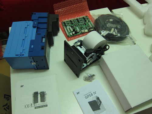
Vending machine parts: bill acceptor, control board, thermal printer.
The parts arrived quite quickly (as a reference, 3 days ago), within less than a week of the order, because they were in stock. Unpacking is fun, though soon it was obvious that not everything is smoothly on track.
The guides attached were barely scratching the surface, contained no information on how to make the units work with the computer (i.e. no protocol, no nothing), maximum referring to some software that I didn’t have access to, and would run on Windows anyways as opposed to my Linux system.
Asking and re-asking a bunch of questions to the sales guy made it clear:
the thermal printer does not need the payment system board, and indeed it cannot even talk to the printer (though an attached documentation says the opposite). Need a “main” board to print to it.
the thermal printer on the order was 12V supply and RS232 connection, while mine is 9V and USB, and apparently the former does not even exist. It uses wallplug instead of shared power like the bill acceptor and the payment system board.
the payment system board cannot control the bill acceptor with the current RS232 cable, because its single RS232 connector is for the external “main” board that I should make. If I plug in the bill acceptor in there, the payment system has to be stand-alone
the bill acceptor comes with a power plug which is type 172340-1, that none of the local computer part stores know, so I cannot (easily) supply power to it. They will send me another adaptor cable to improve on this.
Based on all this it seems like that even if they knew my use-case correctly, the actual parts I got do not fit together the way they represented it, and there’s plenty of confusion about the specs. I really didn’t need the payment system board, for example…
All in all, my contact was quite helpful, and pretty quick to reply, though it is still quite painful first encounter with system integration, and there’s a lot more to fix with the hardware, though was good enough to start.
Assembly
There was a lot more querying in the emails about related documentation. Got the description of the ICT-104 protocol to communicate with the bill acceptor (it’s not too bad). Got the windows printer driver for the thermal printer, though managed to use it without that (and installing Windows): it turns out that the printer implements the Epson ESC/POS protocol, for which there’s already a python library, the python-escpos. It seems to be pretty dead, but good enough for initial testing.
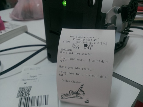
Thermal printer test print
The test prints are “okay”: the text is fine (32 char/line), barcode and qr code should be usable but there seems to be some communication problem that breaks images (like the space shuttle on the above picture), that needs to be debugged (seems like not all gifs are created equal, for example, some are more reliable). Oh, I used Dallas Clayton’s poem, “Good/Bad” for the testing.
Played with the bill acceptor as well, using some pins and a bench power supply (set to 12V, the bill acceptor eats max ~0.6V when the motor is running), and hoped that I don’t blow the circuit… So far so good.
The vending machine flow is something like this:
turn on
read receive address of customer
accept payment
calculate outgoing bitcoin
send payment
print receipt
I was doing the printer testing in Python, and RS232 is pretty easy in Python, so just cobbled together a command line vending machine interface in Python.
Turn on, communicate with the bill acceptor, display some initial information that I know that it’s going well.
Start running zbar in the background to read qr codes from the computer’s webcam. Using the console to exchange information, didn’t have time to fix up the python-zbar integration, though it should work as the Electrum bitcoin client uses it as well.
After an address is read, read the notes of the bill acceptor, and update the sum of received pay. This is listening on the RS232 line for specific codes, and replying to tell the bill acceptor what to do (i.e. accept/reject).
When the user is finished and signaled that to the interface, calculate the outgoing value, send the payment through a payment server. The payment server is a nodejs script that accepts payment information through a REST API. It does it very badly, insecurely, using the wrong REST model (it should be “POST” to do anything with consequence, never “GET”), but it does work. It connects to a local bitcoind instance (over SSL at least, not that it matters in this case, but at least I know SSL will work for the “real” server), which at the moment is connected to the testnet, not the real one.
After the payment is sent, print the receipt with some useful information on it, and a bitcoin logo for good measure.
The current stages of the both the bitcoin vending interface, and the payment server are open source and online. And it worked, here’s a video of it in operation.
Future
I hoped it would be in better stage before tomorrow’s Bitcoin with a Lawyer’s Eyes event in the Taipei Hackerspace, but either way it is good to think ahead further.
If I want to make it really useful, and a “real” machine (one that you can kick or pour beer over it and still keeps working, as one of my friends put it), there are some specific things I can improve:
enclose it in a box: metal, laser cut acrylic, …?
better bill acceptor: keep bills in escrow before the payment gets through, disable acceptance unless we are at that stage of the workflow, set maximum vending amount in one go.
designa a better interface, that can do multiple payments before needing to restart
price not hardcoded into the software but dynamically set
print relevant links embedded in qr code, eg. transaction on blockchain.info
make the payment server secure and improve the overall security, eg. have a code or activation for starting up
hook it up to the proper bitcoin network (this is the scariest part)
build a few more, fund them, and put somewhere accessible
Now back to work.
Ps: My purpose of building any such machine is to make it easier to acquire bitcoins, this spreading their usage and increasing their usefulness. If you feel like tipping, my address is 1GxSUTrw5onv9HbJhKN5PVhuyxm4j75X8d. Thanks!
It didn’t take the arrival of a horrendous electricity bill to the Taipei Hackerspace to start thinking about reducing my electricity footprint. In the last half a year there were two solar power projects on Kickstarter that I signed up for: the Solar Pocket Factory (SPF), and the Foldable USB Solar Cell (FUSC). Generally there’s a lot of sunshine here in Taiwan (when we don’t have a typhoon), and even if I cannot power my laptops from it, could certainly try to power my smartphone…
It turned out that I needed both Kickstarter projects to make one good device.
The Foldable USB Solar Cell looks awesome and not bad at 7W and 5W (the two pieces I have). The voltage output doesn’t seem to be very stable, or has strange behaviour as it doesn’t charge my attached phone when there’s too much direct sunshine. Thus I cannot really use this directly with devices.
The tiny solar panels in the Solar Pocket Factory are very fragile and I couldn’t really make them into an actual working cell yet. On the other hand, it came with a 2000mAh battery and a circuit called Li-Po Rider Pro, by Seeed Studio. This circuit us solar cell or USB input to charge a battery , plus have a good output circuit to charge a USB device either from the battery when there’s no sunshine or from the input when there is.
Putting together the Foldable USB Solar Cell and the Li-Po Rider Pro, we have something that kicks arse indeed! Since I only have one circuit and Seeed doesn’t seem to sell it separately, I thought I could improve on things if I use both solar
USB adapter for parallel panels
The easiest idea I could come up with is creating a USB adapter to connect the panels in parallel (thus practically summing them up as current sources).
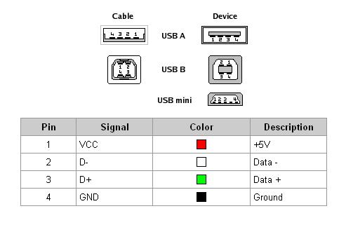
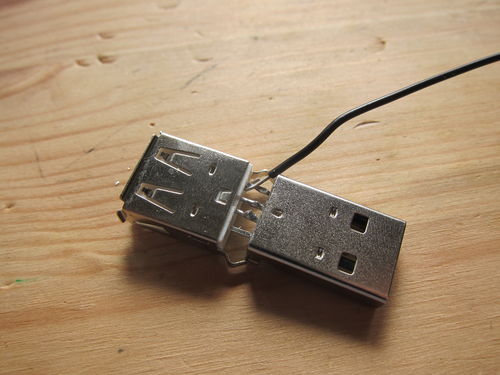
This plan needs two male USB A connectors (the “cable” type on the picture) to plug into the panels, and one female USB A (the “device” type) to provide the single output. Then female VCC pin is wired to both male VCC pins, and the GND pin similarly to the GND pins. The D-/D+ pins are not in use in this case.
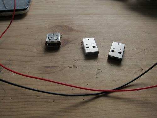
Part for the solar panel connector. One female and two male
The connectors came in as $0.40 each, the wire I don’t remember but probably a few cents. I fortunately had both black and red to use with the GND and VCC. Things are better colour coded.
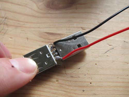
Soldering together the middle two pins, and hook the ones on the side with wires (here the black wire for the Ground line)
First the middle two pins of a male and a female connector is soldered together, just to provide mechanical support. The end of the cable is stripped and hooked around the touching pins (the GND pins on this picture). The two pins + wire is then soldered together, with enough solder to stay, but not that much that the other pins could touch.
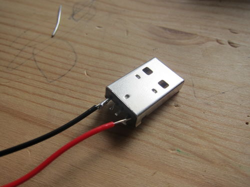
Finished soldering, a bit too much solder, but at least it holds
Did the same thing for the VCC pins + red wire. Finally added some more solder to the central pins. It was pretty stable like this, though I guess it would be better to have some sort of external housing for it or another way to increase the mechanical rigidity of the connection.
The extension cord to the extra male connector
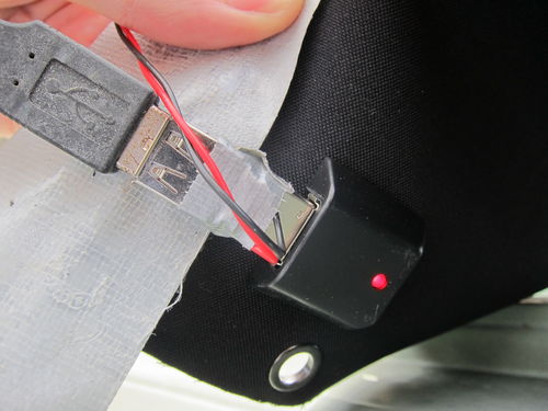
Finally the other connector is soldered, making sure that the right pins are connected (the same as the other male USB). The connectors are then wrapped in a bit of duck tape for some rough insulation. These parts will be outside, both in sun and rain, nothing much can break, but better not test whether I’m right about this particular point…
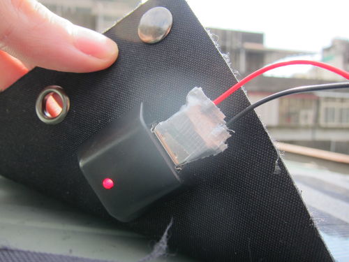
Cover and plug into the secondary solar panel
Plugged into the secondary (5W) solar panel, and into the primary (7W) one as well. Duck taped everything down onto the roof well enough that they are not blown away too easily (though I’d better check on them in a bit, the wind is howling just now outside).
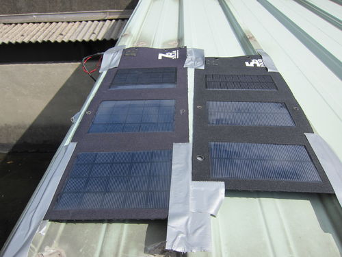
Primary solar panel with the adaptors
As an aside, the duck tape doesn’t seem to like the sunshine. It sticks its sticky parts on everything, that part doesn’t seem to spell fun for the future.
Ready to charge
When everything is connected, the panels will get pretty good sunshine for the bigger part of the day. I don’t think they reach max capacity, because the angle is never ideal, but from the practical point of view, they get enough sunshine to max out the attached 2000mAh battery between device charges.
Hold the panels down, plenty on sunshine (at least this afternoon
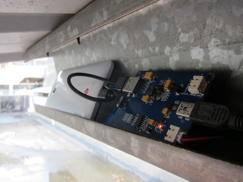
The Li-Po Rider Pro circuit is under the roof, so it doesn’t get any rain (at least I hope!), and has a little ledge to charge a phone safely as well.
Charging circuit and filling up my phone
Since all the devices were pretty much full when I checked in the Hackerspace after I finished this setup, the test whether combination of the two solar panels does indeed increase the power is not foolproof. Otherwise I would have charged a device from a low battery level to a bit higher with one panel, then later switch to two panels and see the different slope of the batter charge versus time. Normally at high charge levels (90%+) the slope is varied by the charging circuit (to preserve the lithium battery’s life), thus that level is not really good to test the difference between the single / dual panel situations.
One thing does suggest, though that the plan worked. Before this modification, charging a phone discharged the Li-Po Rider Pro’s own battery (there’s a touch switch on the circuit to get an approximate charge level, indicated by the lighting up of 0 to 4 LEDs on an LED bar), even in full sunshine. This time it seems that both the phone and the storage battery is charged up, indicating larger incoming power than before. I will check it again next time, though (the Nexus 7 tablet we have will be great for that, it has much larger internal battery than my HTC Butterfly phone)
Possible improvements
There are a few things I could improve on the setup, focusing on usability.
I hope to get a longer USB cable to reach from the roof to inside the Hackerspace, and set up a charging station within the room. This way people don’t have to keep their devices out of reach while charging, and there’s no chance of being ruined by a sudden rain.
I hope to get a larger capacity Li-Po battery. 5-10.000mAh could be good, then it would likely have enough power all the time to keep charging people’s devices, and not standing idle being full when not charging something, while easily emptied by a single device.
The roof also has plenty of more space, so getting a bunch of other panels, combined with the first two upgrades, would make it really beneficial. These foldable panels would be better portable, and keeping them in one place feels a sort of waste.
Ultimately it would be awesome if I could have a purely solar-powered phone. Because it would mean some money saved, but also, and mostly, because I can.
I sure felt different yesterday morning waiting for my turn to give my 30 minutes talk, but in retrospect I’m really glad to have been invited to the Boost Open Source Hardware Movement event, organized by the CTIMES magazine over here in Taiwan. It was the second time try, after Typhoon Soulik cancelled the original event.
Kicking off the event early Saturday morning
There were 8 speakers scheduled from different companies and background: RS Components, Via, Broadcom, Motoduino, TMI Holding…. and me from Taipei Hackerspace. First I was wondering how do I fit in there, and maybe my talk *was* out of place a bit. Most talks were in Chinese so I could grasp only basic stuff from them, although the slides helped – most people made slides following the “slides are my notes” style, which is not my style, but was welcome this time. It was also great to see seasoned speakers like Richard from Via, and Lucas from TMI giving fun (and informative!) talks.
I did feel I’m in the right company, though. Open Source Hardware is becoming more and more of my focus – or maybe I’m just realizing it now that what I do is called such. Part of the audience were industry professionals and part enthusiastic hobbyists & students, and I had some great chat in the breaks with both kind of people.
I heard about the National Science Fair here (what? I got to check that out!), and how much interesting work people do with interactive hardware and elementary/high school kids. There is waaaay more going on that I can imagine, and there’s a lot more potential to tap into.
Had a chance to gather some industry experience too. Naren from Broadcom, who was responsible for getting Raspberry Pi into production was telling the story how they were expecting only 10,000 orders altogether and got 350,000 on the first day (sold 1.8 million to date), so they had to scramble an entire new supply chain. Thought that came to me was that maybe that’s one of the biggest value of Kickstarter/Indiegogo is to be able to get an order of magnitude estimate of the demand.
Also heard about Via’s experience in pursuing new design and materials with their APC platform (such as using paper for housing), and interacting with their community. Heard a lot from RS Components how they are building tools for their community, and building the community itself. The demo was fought with technical difficulties (first rule of presenting is not to assume a working/fast internet connection), but it was inspiring nonetheless, and gave me some big (and difficult) ideas for my project: have to see if there’s any good community for scientific/laboratory electronics and hardware building, and if there isn’t then build one.
Break time between the talks, everyone’s scrambling for chat and cakes
One of my favorite part in these events though to meet friends’ friends. This time was no exception, even if there was too little time to talk, I left with quite a few people in mind who I will need to contact soon, because they are doing something awesome and connected to my area of interest, either in hardware or in startups. This is one reason I’m trying to be really generous with my time and making introductions between people who I recon would hit it off well: I was the recepient of that so many times that I got to give back too.
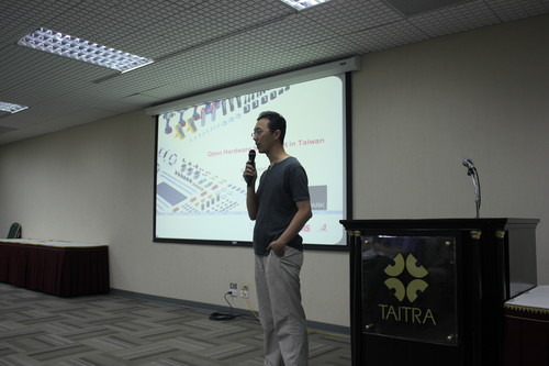
My talk
I was scheduled in the middle of the afternoon just before tea break, and I was one of two people who used English for their talk (out of the 8 speakers). I was more nervous
My favorite part writing this talk was probably the attempt to summarize the philosophy and values of the maker movement, in a way that would inspire others. Some bits:
Don’t accept crappy – everything can be changed and improved upon.
Aim for collaborative creation. Celebrate the weird. Don’t mock.
Do and then share the results for everyone to learn from it.
For things to happen, you have to show up. Don’t wait for someone else to start, build up and inner motivation
Everyone’s values are different, a ‘space is often a different canvas for everyone.
So far the feedback I got about the talk is that I should have mentioned the projects people were working on in the ‘space, and upcoming events. That would have made a better ending for sure, and I had an extra 5 minutes or so to do that. Definitely going to emphasize the practical aspect next time.
Another thing I noticed listening to (a bit of) the video is that I need to use much less “ehm” and “ahm”… I certainly don’t remember using any, and consciously trying to avoid it in my talks in the recent years, I guess I need to listen more carefully (and prepare better).
Any more suggestions? What else wasn’t good? Bring it on, I want to become better at this.
More about the Taipei Hackerspace is on the mailing list, which is open for everyone to sign up, ask questions, show their projects, and hear more about what’s up.
My involvement in the Taipei Hackerspace so far had two very beneficial effect on my thinking: first I have much more ideas what new things to create, then I have much higher probability of seeing those projects through to completion. This post is a write-up of a recent project, illustrating both of these points.
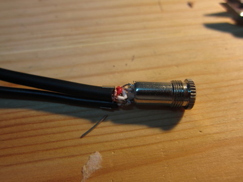
About two weeks ago, I have fixed a headphone for a friend: the wire near the jack was broken and needed replacement. It was a relatively straightforward project, but needed a bit of digging into audio wires and jack connections. I was really proud of the result (fixing things have this effect, I highly recommend doing more of that!), and kept thinking if I can come up with any other audio-related project where I can use the knowledge I learned, and this is what I have came up with:
I bring my laptop almost everywhere with me, and started to use my smartphone headset to listen to music since it sounds great and much lighter to bring with me than the large headphones. It also has a built in microphone, so if I can use that, then really don’t need any other equipment to make Skype/Google+ Hangout calls. Those are 4-conductor headphones for Left/Right/Ground/Microphone channels, but computers (PCs) can only use the 3-conductor Left/Right/Ground and Mic/Mic/Ground connectors. Let’s make an adapter so I can break out the audio lines and mic lines to the appropriate laptop connectors!
Hardware setup
The parts needed:
1pc 4-conductor input socket
2pc 3-conductor output jack
1pc 1-signal (mono) audio wire (signal + ground lines), about 15cm per finished adapter
The Guanghua Computer Market and its neighbourhood has a lot of electronics stores. The appropriate output 3-conductor jacks were really easy to find, as were the audio cables. Those didn’t look as good as the Bose headphone that I repaired, but it’s good for a prototype. The hardest part was the 4-conductor input socket: they had some that should be mounted on a printed circuit board, and tried that one for the first prototype, but then they found me some better one that I can use with the cables. That was the most expensive part at about 20TWD ($0.70).
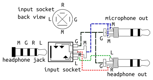
Wiring diagram of the whole cable, M=microphone, G=ground, R=right, L=left
Above is the circuit schematic, probably a bit of a mess, but tried to keep it simple. Then aim of the whole setup is to get the G (ground) + M (mic) lines to one jack (the mono audio, thinner cable), and G + L (left) + R (right) to another (stereo audio, ticker cable).
One complication is that the order of M-G-R-L seems to be the “Apple Way”, that my HTC headphone adopted as well, while others have a more logical (and easier to solder) G-M-R-L series (eg. the Sony PSP headphones as I found searching for it). Thus this adapter would not work for every headphone. Maybe version 3 should have a switch to swap the Mic and Ground lines at the input socket?
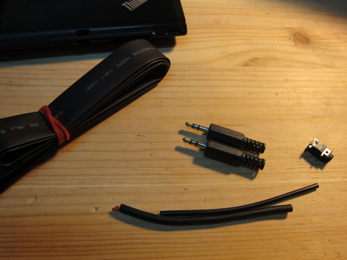
Version 1 of the adapter: 2 pieces of 3-ring jacks, 1 piece 1-line wire (that is signal + ground), 1 piece 2-line wire (2 signal + ground). The input jack is different for the final version, and heatshrink will not be needed.
After all the parts are collected, there’s some micro-surgery. Strip the audio wires carefully, and don’t have to leave much out, just enough to get to the jack electrodes, and such that the thick outside cover fits into the cramp that is there to hold things in place.
For the microphone wire, connect the two output channels (the tip and the 2nd ring), and the ground goes to the base one. For the audio output, the tip is the left channel, the 2nd ring is the right, and the base is ground. The audio wire I got was a bit thick to cramp, but it’s not too bad if the metal cuts into the plastic cover, as long as it doesn’t cut through it.
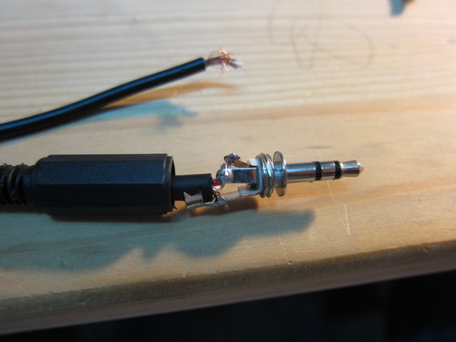
Soldering one of the output jack
The input socket was quite a bit trickier to solder, because the electrodes were so tiny. They are arranged in a 4 directions, going around clockwise as “tip – 2nd ring – 3rd ring – base”. Had to use some magnifying glass and one spare unsoldered jack to make sure I connect the right things to the right places, but it works – mostly. The hardest part is not to melt the individual wire insulation (they are not enameled wired as inside the manufactured headphones). Also, cramping the two wire together is tougher, had to cut off the sleeve of the socket so the wires fit within the plastic cover of the socket.
Soldering the input socket of the final version, that’s pretty tight for the two wires, have to make sure not to burn off the plastic cover or them
This second version was done within about 15-20 minutes, though, since I had all most of the research done previously. Had to do some careful inspection that no shorts developed within the device because of the soldering, and then connect everything up.
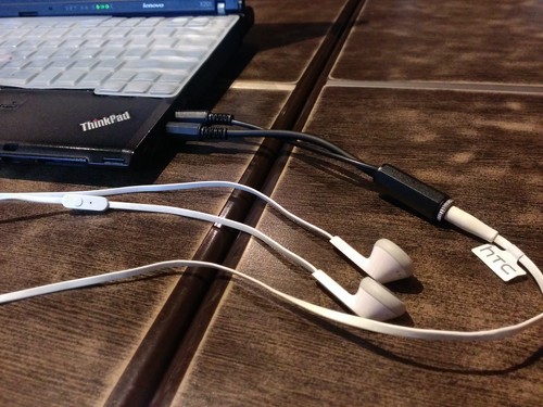
The final design together with HTC Butterfly headphones, with the microphone visible on the left
The listening sound quality is pretty good, though I guess it could be improved with better soldering (which includes using a finer tip soldering iron), and more patient cabling work. The mic is pretty nice, my recordings sound much better than before, and it’s convenient to use too. Much less thing to carry around and definitely better than my laptop’s built in mic. This might even get me to make more calls (sorry Mum and Dad that I haven’t been phoning too much lately!)
Taking it further
The electronic markets here in Taiwan are full of gadgets, and I looked but couldn’t really see any commercial adapter that did the same thing. This made me think that maybe it could be interesting to make this into an actual product. First find some local factories that could make it, as I keep hearing my business-related friends manufacturing a lot of things. Then set up a Kickstarter/Indiegogo project with some reasonable (let’s call it hobby-level) financial goal, and see whether people would be interested.
This would need quite a bit of preparation, and what’s putting me off is the simplicity of the project (what’s too simple for Kickstarter?), and that a Chinese factory could rip it off faster then you can say Shenzhen. Still, it might worth it for the experience and contacts, will do some research, and in the meantime keep making stuff that interests me.
Update 8/6: as a commenter pointed out, these things exists already e.g. on Amazon, searching for “smartphone headset pc adapter”. I guess that simplifies the future a bit, have more time for better projects.