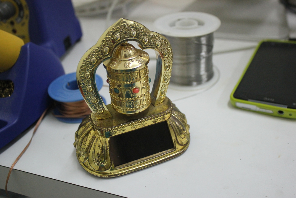
There are all kinds of toys and fun gadgets around the house for most people that might work or be broken, but either way most people wouldn’t know how do they work inside. For example take this solar powered Tibetan prayer wheel. There are many of these out there, and found one at home lying around as well. It didn’t seem to work, and thought why not take apart to take a look?
Solar powered Tibetan prayer wheel
The inside of this Tibetan prayer wheels is pretty straightforward: taking off the bottom cover out come two ballast stones, and drivebox with a solar panel hanging off it. The drivebox is connected to the prayer wheel outside via a rectangular shaft to turn it.
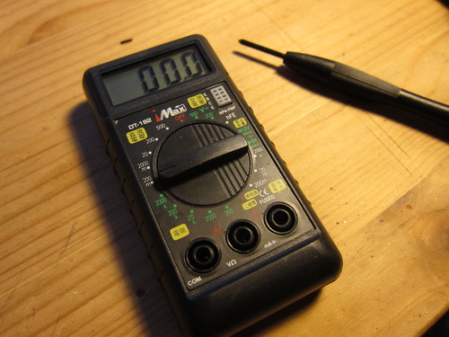
A recent simple battery change operation of a small multimeter (DT-182 or a clone of thereo) turned into a disassembly, when I heard a little rattling noise when shaken after I put in the new battery. I was curious if there was anything loose inside the box. Took some pictures of the inside of the multimeter, and added some notes to how things seem to work. I try to guess the origin of the design choices within hardware, in a way to learn a bit about hardware manufacturing.
Disassembled
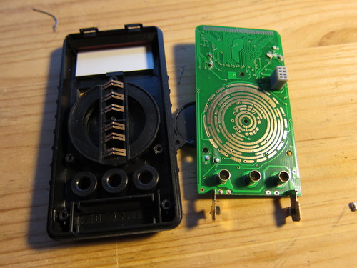
The first thing I did is unscrew the PCB and see whether anything is between that and the front of the housing.
Multimeter: board out
The things I noted here: the knob, the screw hole placement, and the LCD-PCB interface.
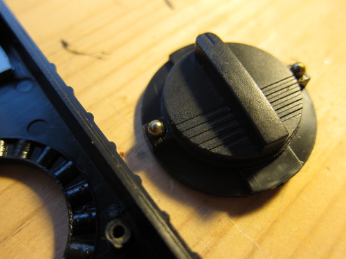
Now I understand a bit better how the knob works: the little metal brushes make contacts differently for different position of the knob, and the control electronics knows the required functionality based on reading those connections (specific shorts? specific resistances? that I forgot to check). The brushes are weird a bit too: one fell off and I tried to put pack but didn’t see how it could be attached. Turns out, that the slit in the middle is a bit narrower than a plastic edge underneath, and the brush sticks on to that (barely). When pressing agains the board, the triangle shape can flatten, and keep physical contact. There’s also a whole for the knob centre that is not screwed, but keeps the knob from wandering
The screw hole placement for the PCB is in a triangle shape around he knob. I think it’s a good way to keep things tight with the smallest number of screws.
The LCD interfacing is pretty weird. The display segments of the LCD are controlled through the big bunch of lines on the top of the board. That is touching a rubbery contact stack on the top of the LCD. I guess it’s rubbery because it needs to be able to compress easily. I wonder what’s the conductive material within that . There’s also a plastic bar that the PCB pushes down and which in turn pushes the display down, i.e. into its place of the exposure. I think it’s a quite cool way for easy assembly but holding things quite securely in place. The PCB slips into some slot on the top the enclosure, and pushed into place on the bottom (the metal tubes go into the plastic holes, and the electrodes into their respective slits).
Multimeter: the knob
Taking the knob off, it’s held in place by the balance of the PCB pushing down on its back, and a pair of ball bearings. There’s a spring under each of the bearings, which is within a plastic hole, while the ball is a bit larger than the whole, so it cannot be stuck inside of it. The positions of the knob are set by the holes in the plastic ring (on the left of the image. The balls are greased somewhat, quite sticky. Putting things back together was a bit tricky, not letting the balls fall out on one side, and the brushes to fall off on the other.
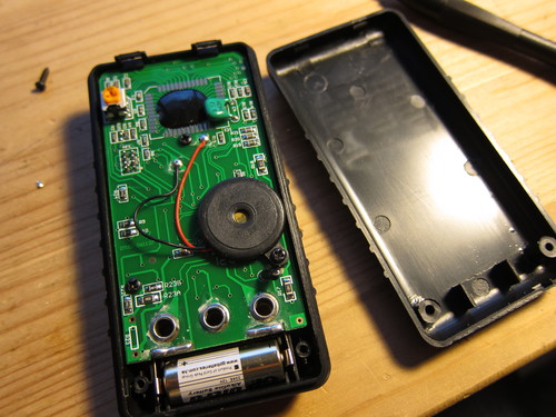
Multimeter: board back
The PCB is secured to the front assembly with three screws. One of them also holds a buzzer in place and that screw is a bit longer – thus not all screws are the same in this gadget.
The backplane has a pair little grooves on the top which fit into the two hinges on the top of the frontplane (I really wonder what’s the proper name for those parts…). Other than that, two screws on the bottom secure the back. The battery is held in place with two plastic legs (between the screws of the backplane).
Back in working order
After the second try, I could put everything back and the multimeter seems to work.
Funny thing, when I shake it I can still hear the rattling noise. Now that I’ve seen the inside, looks like it’s the plastic piece that should help to hold the LCD down, so probably it’s smaller than in the other multimeters like this we have, or the PCB is not fastened as much as it is supposed to. Though I don’t like over-fastening metal screws in plastic threads – recipe for shredded threads.