There are all kinds of toys and fun gadgets around the house for most people that might work or be broken, but either way most people wouldn’t know how do they work inside. For example take this solar powered Tibetan prayer wheel. There are many of these out there, and found one at home lying around as well. It didn’t seem to work, and thought why not take apart to take a look?
Solar powered Tibetan prayer wheel
The inside of this Tibetan prayer wheels is pretty straightforward: taking off the bottom cover out come two ballast stones, and drivebox with a solar panel hanging off it. The drivebox is connected to the prayer wheel outside via a rectangular shaft to turn it.
It didn’t take the arrival of a horrendous electricity bill to the Taipei Hackerspace to start thinking about reducing my electricity footprint. In the last half a year there were two solar power projects on Kickstarter that I signed up for: the Solar Pocket Factory (SPF), and the Foldable USB Solar Cell (FUSC). Generally there’s a lot of sunshine here in Taiwan (when we don’t have a typhoon), and even if I cannot power my laptops from it, could certainly try to power my smartphone…
It turned out that I needed both Kickstarter projects to make one good device.
The Foldable USB Solar Cell looks awesome and not bad at 7W and 5W (the two pieces I have). The voltage output doesn’t seem to be very stable, or has strange behaviour as it doesn’t charge my attached phone when there’s too much direct sunshine. Thus I cannot really use this directly with devices.
The tiny solar panels in the Solar Pocket Factory are very fragile and I couldn’t really make them into an actual working cell yet. On the other hand, it came with a 2000mAh battery and a circuit called Li-Po Rider Pro, by Seeed Studio. This circuit us solar cell or USB input to charge a battery , plus have a good output circuit to charge a USB device either from the battery when there’s no sunshine or from the input when there is.
Putting together the Foldable USB Solar Cell and the Li-Po Rider Pro, we have something that kicks arse indeed! Since I only have one circuit and Seeed doesn’t seem to sell it separately, I thought I could improve on things if I use both solar
USB adapter for parallel panels
The easiest idea I could come up with is creating a USB adapter to connect the panels in parallel (thus practically summing them up as current sources).
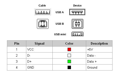
This plan needs two male USB A connectors (the “cable” type on the picture) to plug into the panels, and one female USB A (the “device” type) to provide the single output. Then female VCC pin is wired to both male VCC pins, and the GND pin similarly to the GND pins. The D-/D+ pins are not in use in this case.
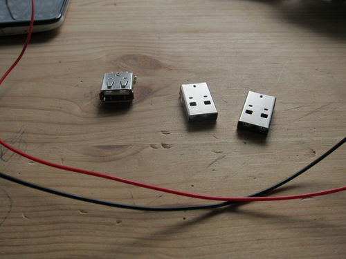
Part for the solar panel connector. One female and two male
The connectors came in as $0.40 each, the wire I don’t remember but probably a few cents. I fortunately had both black and red to use with the GND and VCC. Things are better colour coded.
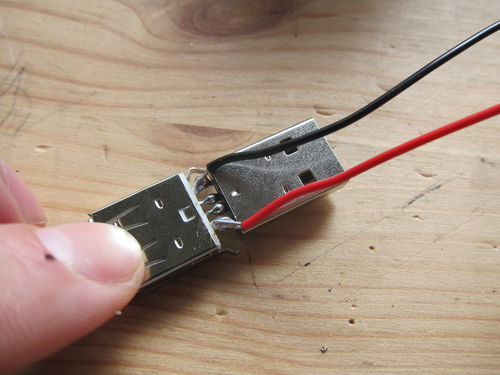
Soldering together the middle two pins, and hook the ones on the side with wires (here the black wire for the Ground line)
First the middle two pins of a male and a female connector is soldered together, just to provide mechanical support. The end of the cable is stripped and hooked around the touching pins (the GND pins on this picture). The two pins + wire is then soldered together, with enough solder to stay, but not that much that the other pins could touch.
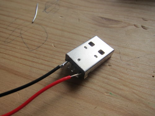
Finished soldering, a bit too much solder, but at least it holds
Did the same thing for the VCC pins + red wire. Finally added some more solder to the central pins. It was pretty stable like this, though I guess it would be better to have some sort of external housing for it or another way to increase the mechanical rigidity of the connection.
The extension cord to the extra male connector
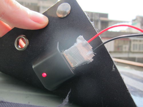
Finally the other connector is soldered, making sure that the right pins are connected (the same as the other male USB). The connectors are then wrapped in a bit of duck tape for some rough insulation. These parts will be outside, both in sun and rain, nothing much can break, but better not test whether I’m right about this particular point…
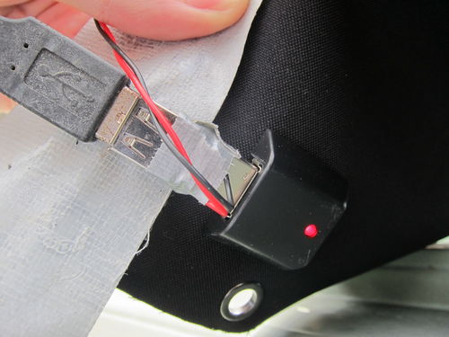
Cover and plug into the secondary solar panel
Plugged into the secondary (5W) solar panel, and into the primary (7W) one as well. Duck taped everything down onto the roof well enough that they are not blown away too easily (though I’d better check on them in a bit, the wind is howling just now outside).
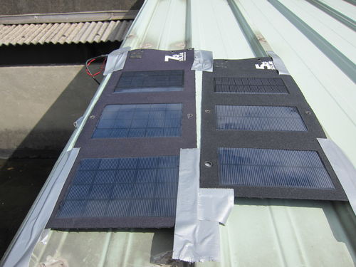
Primary solar panel with the adaptors
As an aside, the duck tape doesn’t seem to like the sunshine. It sticks its sticky parts on everything, that part doesn’t seem to spell fun for the future.
Ready to charge
When everything is connected, the panels will get pretty good sunshine for the bigger part of the day. I don’t think they reach max capacity, because the angle is never ideal, but from the practical point of view, they get enough sunshine to max out the attached 2000mAh battery between device charges.
Hold the panels down, plenty on sunshine (at least this afternoon
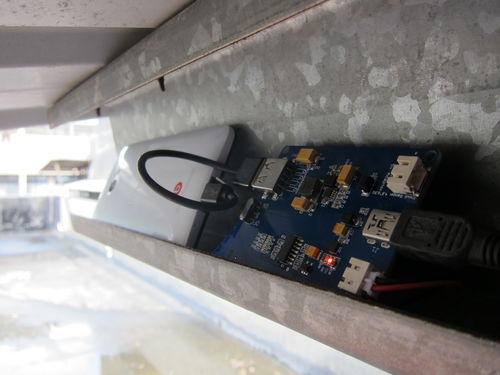
The Li-Po Rider Pro circuit is under the roof, so it doesn’t get any rain (at least I hope!), and has a little ledge to charge a phone safely as well.
Charging circuit and filling up my phone
Since all the devices were pretty much full when I checked in the Hackerspace after I finished this setup, the test whether combination of the two solar panels does indeed increase the power is not foolproof. Otherwise I would have charged a device from a low battery level to a bit higher with one panel, then later switch to two panels and see the different slope of the batter charge versus time. Normally at high charge levels (90%+) the slope is varied by the charging circuit (to preserve the lithium battery’s life), thus that level is not really good to test the difference between the single / dual panel situations.
One thing does suggest, though that the plan worked. Before this modification, charging a phone discharged the Li-Po Rider Pro’s own battery (there’s a touch switch on the circuit to get an approximate charge level, indicated by the lighting up of 0 to 4 LEDs on an LED bar), even in full sunshine. This time it seems that both the phone and the storage battery is charged up, indicating larger incoming power than before. I will check it again next time, though (the Nexus 7 tablet we have will be great for that, it has much larger internal battery than my HTC Butterfly phone)
Possible improvements
There are a few things I could improve on the setup, focusing on usability.
I hope to get a longer USB cable to reach from the roof to inside the Hackerspace, and set up a charging station within the room. This way people don’t have to keep their devices out of reach while charging, and there’s no chance of being ruined by a sudden rain.
I hope to get a larger capacity Li-Po battery. 5-10.000mAh could be good, then it would likely have enough power all the time to keep charging people’s devices, and not standing idle being full when not charging something, while easily emptied by a single device.
The roof also has plenty of more space, so getting a bunch of other panels, combined with the first two upgrades, would make it really beneficial. These foldable panels would be better portable, and keeping them in one place feels a sort of waste.
Ultimately it would be awesome if I could have a purely solar-powered phone. Because it would mean some money saved, but also, and mostly, because I can.
It is very much summer now here in Taiwan, and if one thing the Tropics is good at, then it’s being hot and humid. That’s sometimes fun, when there’s enough chance to hang out by a pool or on the seaside, but most of the time not that much. That’s why there are so many air conditioners, and other clima controls.
As I really like data, and this place is great for electronics, I thought I can just combine the two things, and try to learn more about my environment. Temperature is relatively easy, but for a long time I was looking for a humidity sensor. At the local electronics market I found a few different models the other day, and got one of them – pretty much the cheapest one, because all the manuals were in Chinese anyway (which I don’t yet read), and they were also all packed up, so there was not much peeking anyway. There was a combined temperature/humidity sensor board (two sensors already packed up together), but at 450NT it felt pricey and needed to buy some connectors for it as well. There was a larger round capacitive sensor, but it was too large for my liking.
I ended up with a “CM-R Resistive Humidity Sensor” (here’s an English spec scheet for it). It was 250NT (~5 quid or 8 bucks) which makes it relatively expensive equipment for me, though maybe because I was saving my cash in my wallet for going to Mobile Monday Taipei later that night. Still, if it works then it does worth it, and might get a few more pieces.
Wiring it up
I never actually knew how the electronic humidity sensors work, so this is a good primer for that. Nevertheless, the plan was afoot to hook it up to an Arduino and measure some RH% (relative humidity). It was quite tricky for me to figure out the wiring, though, because I never worked with resistive element that could handle only AC voltage, and gets destroyed by DC.
That white rectangle with black spots, the humidity sensor at work, all plugged in with Arduino
Fortunately there were a couple of people (indeed just 2 or 3 that I could find) who were working with this, and had some good information. The one I went with was this post from the Arduino forums. Was quite informative, though I think the final formula is faulty – not because I understand it completely (my electronics theory is spotty at best) but because experimentally I figured out what works instead (being an experimental physicist, that’s pretty much what I do all day anyway).
Finally it is hooked up something like what is shown in this hideous schematics (really got to find some better way to draw this):
Humidity sensor schematics, done with Fritzing
After this wiring, I have to switch the digital output (DO) pin between High and Low at about 1kHz with 50% duty cycle. When the pin is on High value, every now and then I measure the voltage with the analog input pin. From the measured voltage I can deduce the resistance of the humidity sensor as
RH = R1 / ((Vref - Vm) / (Vin - Vm) - 1)
where Vref is the reference voltage (5V of the digital pin), Vin is the measured voltage, Vm is in this case Vref/2=2.5V, the voltage that the capacitors are charged to during all this switching, and R1 is the reference resistance. It works very well, I tried to measure some fixed resistances, and the results are pretty accurate.
When we have the resistance value, the spec sheet has a look-up table for translating the resistance into relative humidity (RH%). It’s quite cumbersome, because will have to interpolate between values, and it’s also not that accurate if the temperature is not known. On the other hand, the values from 25℃ can be used pretty well for all normal temperature ranges here in the summer (let’s say air conditioned 21℃ to outside summery 33℃) with maybe ±5% error in the humidity measurement, that’s not that bad.
The sensor itself feels really sensitive, just having it in the lab, could sense changes in RH as others were doing water-related things the next room. Even if reading is not that accurate, it is still quite precise, and for most of the things it is still okay. I could try in different environments, like our “dry box”, which maintains ~20% humidity, but that means quite high resistance of the sensor, MOhm instead of tens of kOhm, so the voltage reading just moving around near 5V, making it not that precise and noisy as well. For 30-90% humidity it works pretty well, though.
To monitor the readings, I wrote up a quick web-app from some reused code with NodeJS, Express, Socket.io, node-serialport2 and Flot. There’s no kill like overkill, but at least I can already monitor it from any other computer as well, it’s real-time, and the GUI is much easier to adapt than most other ways I know.
All the code for the Arduino and the monitoring server is in my Weatherstation repo on Github. It’s pretty buggy and not documented, will clean that up later when I’ll have a good working version.
Deployment
Now let’s get down to some real action. Being at home, I often feel that my flat is way too humid. Firing this circuit up, I got a reading of 80-85% relative humidity, that’s not something to sneeze at. Then turned on the air conditioning in dehumidifier mode, and watched what happened.
First there was an increase of the relative humidity, because the drop in temperature is quicker and the drop in water content. After chilling for a while, this is how it looked like.
Humidity logging while running the AC’s built in dehumidifier (RH% vs time in minutes)
Looks like some funky periodic behaviour, but empirically I felt much better, even if the humidity didn’t drop much. Maybe the extra comfort comes from the temperature drop as well, so will try to do the same thing in the usual temperature-control-only mode as well, see what does that one look like? I haven’t had neither my laptop battery charger, nor a spare battery with me, so I couldn’t run this too long, I wonder what level it would reach over a longer time. Looks like it has a downward slope, but it’s hard to tell.
Also, the wobbles are likely because of some feedback control that is turning the dehumidifier inside the AC on and off, and that controller has a huge hysteresis. It is not totally surprising, though: as much as I know, dehumidifiers are just big cold surfaces and the water condenses on them from the passing air. For that you have to keep a large surface pretty cold, and it is likely some time to cool a surface or let it warm back up again, thus the controller likely overshoots in both the de- and the re-humidifying parts of the process.
From what I have tried, it feels like a pretty good sensitive sensor, and coupled with
Plans
I’ve seen another way to wire up the sensor in a tutorial, which is basically a resonant circuit and the chance of the sensor’s resistance will change the output frequency. That frequency can be readily measured with Arduino already, so if I get the few extra components, might give it a try. It seems that potentially it can have better noise characteristics then the method I’m using.
Want to add some real logging function to it, maybe saving readings and timestamps into an SQLite database, which I can analyze properly later with Numpy. Or maybe store it in MongoDB, on which I can still interface and do some concurrent analytics even when the sensor is running. Or maybe I consider that just because I use Mongo for Friendcare?
Would like to add a 10-LED light bar, which could display the humidity decades without any computer, thus making the whole setup so much more portable. Though for that I will definitely have to revive a 74HC595STP16C596 Serial-in/Parallel-out shift register, because then I’ll need one resistor and a single DO channel to control those LEDs, instead of 10 DO channels and 10 resistors.
Could also add an LCD screen like this SparkFun SerLCD. The only problem is that it interferes with the serial connection, so might not be able to use it together with the computer monitoring. Might worth it, though, that LCD I have (white-on-black with backlight) looks pretty darn funky.
Could also add some long-term monitoring and some other sensors, to build up a real home weather station. I have my eyes on a barometric pressure sensor, but that’s quite expensive.
Update (2012/11/6):
Been using this in our laboratory for almost two months now, it works quite well, though still thinking of there’s any better way to measure the resistance of the sensor. Brushing up on RC circuits is in order?
Looks like I’m not the only one thinking about humidity sensors and data logging: there’s also another post from the awesome Tom Igoe.