Categories
Admin Maker

Personal phone server, or Can you hear me now?

Ever since someone donated an IP phone to the Taipei Hackerspace, I’m trying to find time to set up an internal phone network between the hackerspace members. It should be fun to make our own infrastructure. Recently did some research, and started with it. Since if I get into something then I dive deep for a while, this was an intense week. This post is to summarize where I have got in this time

Asterisk & FreePBX

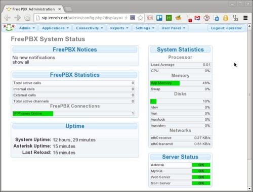
A bit of searching turned up Asterisk, a PBX (“private branch exchange” aka telephone network) software. It looked interesting because it came with a story: a guy building something awesome because he doesn’t know that it was supposed to be difficult. It’s also open source from the start, with a successful company build on top of the project.

Also found, that there’s a graphical control panel called FreePBX that makes using the all-command-line-and-config-files Asterisk easier to use. Both projects had a seemingly very detailed wiki, long track record, and strong following that made it worth checking them out.

The Server

Judging from the original install instructions on the FreePBX wiki, it looked like installing Asterisk & FreePBX is a complex (or rather many-step) process. Didn’t want to litter my own computer with broken installation artefacts, so enter VirtualBox. Using a virtual machine makes it easy to wipe and restart.

There’s a dedicated, preinstalled FreePBX distro based on CentOS, but had enough of CentOS for a while. Instead I just took Ubuntu 12.04.3 as a base, and FreePBX 2.11 and Asterisk 11 from the wiki. The install instructions were clear enough, though occasionally there were small differences needing a fix. Nothing major, but had to play around. After 5-6 reinstalls with increasing experience I got the basic functionality working, calls placed between and such, but the performance and sound quality wasn’t really that good. After thinking what could I improve, decided to take the next step: get out of the virtual machine, and up the version numbers (I’m Arch Linux user with a reason, living on the bleeding edge).

Enter DigitalOcean, a hosting provider that I used for other projects before (cheap, fast with SSD, good service). Set up a machine (aka “droplet”) in their Singaporean center (since that’s probably the closest one to Taiwan). I chose the 1Gb memory instance, because from experience with VirtualBox Asterisk+FreePBX maxed out at around that with a few test accounts.

Upping the version numbers I went with FreePBX 12.0 (from git) and Asterisk 12.1.1 (from download), both are testing versions. Asterisk had an extra dependency of libjansson-dev compared to version 11, didn’t check if any of the earlier dependencies are not required anymore.

The information control panel of FreePBX.
FreePBX interface for Asterisk

Got the whole system working (after a few droplet wipes), and played with the installation with a bit more confidence. From initial experience, Asterisk is a bit like the Linux Kernel. It’s modular, complex, focus on reliability, and the “make menuselect” is a familiar environment after years of “make menuconfig” compiling my own kernel. On the other hand, FreePBX is a bit like WordPress. It has its own auto-updater (just like updating plugins in WordPress), loads and loads of menus, focuses on configuration and tries not to let any faulty module take down the system (found quite a few buggy behaviour, so that’s a good idea). The Kernel and WordPress are two familiar environments, so felt home here too somehow.

Asterisk has a bunch of vocabulary that I’m so far barely familiar with, and lots of functionality that I haven’t had a chance to test yet. FreePBX has a lot of functionality too, and still it’s a bit difficult for me to tell where does an Asterisk function (module, resource?) end and one FreePBX function (plugin?) start. The fact is that I got to feel excited about programmable phone routing (with Lua), fax-to-pdf, hotel style wake-up calls, voicemail recording, call tracing, speaking time, simple conference talks, intercom functionality, regardless from whether it’s a module or a plugin…

Some additional server notes: voicemail requires email out for notification, I set that up with Mandrill and postfix. For such testing it might not be important, but good to secure the server at least a bit with fail2ban and ufw (Uncomplicated Firewall), and probably other things I don’t do well yet. Just sayin’.

Accounts / Extensions

Accounts on  the server are the extensions on which someone (or something), a numerical value. The vocabulary and concepts are also new to me, so it took a while to understand how things supposed to interoperate. Asterisk has a bunch of different kinds of extensions, of which I have tried two main ones: SIP and IAX.

SIP

SIP stands for Session Initiation Protocol. As far as I see it is basically a messaging protocol, to set up a connection between two parties, and also provide some other services, for example presence information (Online, Away, Busy….), messaging, and what not. The actual data of the call (voice or video) is trhough RTP (Real-time Transport Protocol).

The voice data in the transmission is compressed with one of the many codecs available:

  • ulaw and alaw (G.711) are a pair of the standard codecs, okay quality, one of the basic one to have in any client
  • speex is a variable bitrate codec, haven’t used that much
  • gsm is lower bitrate, but lower quality too (think of crappy cell phone reception voice)
  • G.722 is a hi-def (HD) voice codec, really good! I think beats Skype, and on par with a good Google Hangout quality,
  • G.729 is a non-free codec, shows up here and there, but haven’t had a chance to try it, this is the other HD codec that I’ve seen recommended

In testing, this was some of the learning curve, how to set up clients, and also the server that they can communicate with each other. Who choses the codec (caller, callee, server)? How to prioritize the codecs in different clients? What does it look like (or sounds like) when there’s a problem in this area? How to debug and fix?

Asterisk 12 has two different SIP channels or components: their classic library (chan_sip), and a rewritten one (chan_pjsip). The latter one is a standalone library that can be used for other purposes as well. SIP usually works on UDP, while PJSIP can do UDP/TCP/WebSockets too, and feels stable and fast. Definitely would use that if I have to choose between these two. Still, it is in test phase (both in Asterisk and FreePBX), so not without headaches.

There are bunch of different clients that I tried:

On Linux:

  • Ekiga is nice, simple, can sign into multiple accounts in multiple networks. Presence information, well integrated into the desktop with notifications and such. Does not seem to be able to handle non-standard SIP ports (which will be an issue further down)
  • Linphone is really multiplatform (Linux, Win, OSX, smartphones…), but it was crashing on me quite a bit, doesn’t integrate into the desktop (no notification just sound on call), and can be confusing with the lot of settings (the control panel looks a mess). Can handle non-standard ports too.
  • SFLPhone is good, works pretty well, simple, and can do IAX communication besides SIP.

On Android:

  • Android actually has full SIP handling capabilities built in for a while now (under “internet phone”). That would be awesome, if there were more information how to set up and use, but in theory a SIP account can be fully integrated into the system.
  • CSIPSimple really impressed me, probably the best working client I found. Integrates with the system (calls are handled as ‘calls’ with all the icons, history, and so on), good sound quality (can use the G.722 codec) and so on.
  • SipDroid, VIMPhone, LinPhone…. these other clients, don’t even remember them, all of them fell short somehow
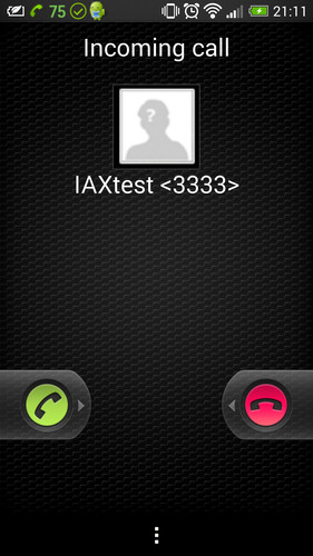
  • Zoiper stands out as well, not just because it’s multiplatform, but because it’s pretty much the only one I found that can do both SIP and IAX. The Android system integration is not as close as CSIPSimple, but quite okay.

One of (the many) good thing about SIP that it is well known and pretty well supported. If there’s a “softphone” (phone in software), it’s quite likely to have SIP communication capabilities.

The bad thing about SIP though that it is well known and pretty well resented by the phone service providers. Many of those providers block SIP messages on their network, or sabotage the connection in some other way. On my own cell phone / 3G provider’s network, I couldn’t connect to Asterisk. In the forums some suggested that changing the port number that Asterisk listens on for SIP connections can solve things – and indeed after moving away from 5060/5061 to somewhere else, I could connect. The celebration was short lived, though because even though the calls now can reach the destination, RTP communication (the part that actually transports voice) was still broken. I don’t want to use VPN all the time (though might need to soon), and want to keep moving parts and settings to the minimum if I want others in the Hackerspace to join this network as well, thus SIP looks like a no-go because of the phone companies (darn).

IAX

Looking around, I found another type of channel, using the IAX (Inter-Asterisk eXchange) protocol. The bad thing about it that it is much less supported, but in turn it is not blocked by the phone companies either (since they don’t know about it).

Using SFLPhone and Zoiper I could successfully talk over 3G! Still it is not all good, the devil is in the details.

Phone interface showing incoming call from IAX test user
Zoiper incoming call on Android
  • It’s good that no need for custom ports
  • It’s bad that the IAX channel seems to be more unstable on Asterisk (or maybe I messed up my install after a while?): some extensions have trouble logging on for a while until the server is restarted; the wakeup-calls plugin misbehaved with IAX extension.
  • The less support also means less choice in clients. The ones I found cannot do G.722 so no HD voice anymore
  • Has a security setting (requirecalltoken) that not all clients support, not sure if there are any implications.

It’s also good, that Asterisk can route incoming SIP calls onto IAX extensions (i.e. the caller doesn’t have to care what technology the callee is using). On the note of routing, I could set things up such that outside calls can be routed into the system. E.g. every hackerspace could have their own Asterisk server and interoperate to call members at other spaces – sounds like a lot of work and might not worth it, but it also sounds awesome.

Summary & Future

I had a lot of fun playing with Asterisk. On the surface phone networks are familiar to everyone, but going deeper both makes things more confusing and opens my eyes how many possibilities there are for making something useful. 

There are a lot of things that I thought about, but haven’t tried yet:

  • Programmable dialplans (“what happens when a call is received”), via Lua. Lua is an awesome language and probably a lot more large piece of software has it embedded (since that’s one of its strength)
  • Could script a lot more too via the Asterisk Gateway Interface (AGI).
  • There are a bunch of other protocols and acronyms in Asterisk, for example Secure Real-Time Protocol (SRTP) and ZRTP, that could worth figuring out for a deeper understanding and security
  • There’s an Asterisk on Raspberry Pi project that looks interesting (if nothing else then how do they lower the memory usage below the RPi’s <512MB?). Since Asterisk can be used with multiple servers in a network, the RPi can provide one kind of service (e.g. GSM gateway) while other servers with more resources do other stuff
  • Using physical phones in the network, for example traditional phone network to come into the server, and IP Phone to ring out.  Maybe setting up fax endpoint (and sending it out as PDF or printing it). Basically anything that is working on the threshold between physical and digital.
  • Should check out how the likes of Line, Voxer, and Viber are doing VoIP on Android, do they have any interoperability?
  • How about Twillio, can their system be a similar PBX on a much larger scale?

The funny thing is that looks like the original IP phone that started this whole adventure does not work with Asterisk. Never mind, it will be good for another project.

Categories
Maker

Peek into a multimeter

A recent simple battery change operation of a small multimeter (DT-182 or a clone of thereo) turned into a disassembly, when I heard a little rattling noise when shaken after I put in the new battery. I was curious if there was anything loose inside the box. Took some pictures of the inside of the multimeter, and added some notes to how things seem to work. I try to guess the origin of the design choices within hardware, in a way to learn a bit about hardware manufacturing.

Disassembled

The first thing I did is unscrew the PCB and see whether anything is between that and the front of the housing.

Opened multimeter with its control board out
Multimeter: board out

The things I noted here: the knob, the screw hole placement, and the LCD-PCB interface.

Now I understand a bit better how the knob works: the little metal brushes make contacts differently for different position of the knob, and the control electronics knows the required functionality based on reading those connections (specific shorts? specific resistances? that I forgot to check). The brushes are weird a bit too: one fell off and I tried to put pack but didn’t see how it could be attached. Turns out, that the slit in the middle is a bit narrower than a plastic edge underneath, and the brush sticks on to that (barely). When pressing agains the board, the triangle shape can flatten, and keep physical contact. There’s also a whole for the knob centre that is not screwed, but keeps the knob from wandering

The screw hole placement for the PCB is in a triangle shape around he knob. I think it’s a good way to keep things tight with the smallest number of screws.

The LCD interfacing is pretty weird. The display segments of the LCD are controlled through the big bunch of lines on the top of the board. That is touching a rubbery contact stack on the top of the LCD. I guess it’s rubbery because it needs to be able to compress easily. I wonder what’s the conductive material within that . There’s also a plastic bar that the PCB pushes down and which in turn pushes the display down, i.e. into its place of the exposure. I think it’s a quite cool way for easy assembly but holding things quite securely in place. The PCB slips into some slot on the top the enclosure, and pushed into place on the bottom (the metal tubes go into the plastic holes, and the electrodes into their respective slits).

The knob of the multimeter opened up
Multimeter: the knob

Taking the knob off, it’s held in place by the balance of the PCB pushing down on its back, and a pair of ball bearings. There’s a spring under each of the bearings, which is within a plastic hole, while the ball is a bit larger than the whole, so it cannot be stuck inside of it. The positions of the knob are set by the holes in the plastic ring (on the left of the image. The balls are greased somewhat, quite sticky. Putting things back together was a bit tricky, not letting the balls fall out on one side, and the brushes to fall off on the other.

The board added back to the multimeter plus the backplane
Multimeter: board back

The PCB is secured to the front assembly with three screws. One of them also holds a buzzer in place and that screw is a bit longer – thus not all screws are the same in this gadget.

The backplane has a pair little grooves on the top which fit into the two hinges on the top of the frontplane (I really wonder what’s the proper name for those parts…). Other than that, two screws on the bottom secure the back. The battery is held in place with two plastic legs (between the screws of the backplane).

Multimeter turned on
Back in working order

After the second try, I could put everything back and the multimeter seems to work.

Funny thing, when I shake it I can still hear the rattling noise. Now that I’ve seen the inside, looks like it’s the plastic piece that should help to hold the LCD down, so probably it’s smaller than in the other multimeters like this we have, or the PCB is not fastened as much as it is supposed to. Though I don’t like over-fastening metal screws in plastic threads – recipe for shredded threads.

Categories
Maker

Smartphone headphone to laptop adapter

My involvement in the Taipei Hackerspace so far had two very beneficial effect on my thinking: first I have much more ideas what new things to create, then I have much higher probability of seeing those projects through to completion. This post is a write-up of a recent project, illustrating both of these points.

About two weeks ago, I have fixed a headphone for a friend: the wire near the jack was broken and needed replacement. It was a relatively straightforward project, but needed a bit of digging into audio wires and jack connections. I was really proud of the result (fixing things have this effect, I highly recommend doing more of that!), and kept thinking if I can come up with any other audio-related project where I can use the knowledge I learned, and this is what I have came up with:

I bring my laptop almost everywhere with me, and started to use my smartphone headset to listen to music since it sounds great and much lighter to bring with me than the large headphones. It also has a built in microphone, so if I can use that, then really don’t need any other equipment to make Skype/Google+ Hangout calls. Those are 4-conductor headphones for Left/Right/Ground/Microphone channels, but computers (PCs) can only use the 3-conductor Left/Right/Ground and Mic/Mic/Ground connectors. Let’s make an adapter so I can break out the audio lines and mic lines to the appropriate laptop connectors!

Hardware setup

The parts needed:

  • 1pc 4-conductor input socket
  • 2pc 3-conductor output jack
  • 1pc 1-signal (mono) audio wire (signal + ground lines), about 15cm per finished adapter
  • 1pc 2-signal (stereo) audio wire (2 signals + ground), same length

The Guanghua Computer Market and its neighbourhood has a lot of electronics stores. The appropriate output 3-conductor jacks were really easy to find, as were the audio cables. Those didn’t look as good as the Bose headphone that I repaired, but it’s good for a prototype. The hardest part was the 4-conductor input socket: they had some that should be mounted on a printed circuit board, and tried that one for the first prototype, but then they found me some better one that I can use with the cables. That was the most expensive part at about 20TWD ($0.70).

Wiring diagram showing the internals of the adaptor
Wiring diagram of the whole cable, M=microphone, G=ground, R=right, L=left

Above is the circuit schematic, probably a bit of a mess, but tried to keep it simple. Then aim of the whole setup is to get the G (ground) + M (mic) lines to one jack (the mono audio, thinner cable), and G + L (left) + R (right) to another (stereo audio, ticker cable).

One complication is that the order of M-G-R-L seems to be the “Apple Way”, that my HTC headphone adopted as well, while others have a more logical (and easier to solder) G-M-R-L series (eg. the Sony PSP headphones as I found searching for it). Thus this adapter would not work for every headphone. Maybe version 3 should have a switch to swap the Mic and Ground lines at the input socket?

Parts for the first version of the adapter
Version 1 of the adapter: 2 pieces of 3-ring jacks, 1 piece 1-line wire (that is signal + ground), 1 piece 2-line wire (2 signal + ground). The input jack is different for the final version, and heatshrink will not be needed.

After all the parts are collected, there’s some micro-surgery. Strip the audio wires carefully, and don’t have to leave much out, just enough to get to the jack electrodes, and such that the thick outside cover fits into the cramp that is there to hold things in place.

For the microphone wire, connect the two output channels (the tip and the 2nd ring), and the ground goes to the base one. For the audio output, the tip is the left channel, the 2nd ring is the right, and the base is ground. The audio wire I got was a bit thick to cramp, but it’s not too bad if the metal cuts into the plastic cover, as long as it doesn’t cut through it.

The output jack image
Soldering one of the output jack

The input socket was quite a bit trickier to solder, because the electrodes were so tiny. They are arranged in a 4 directions, going around clockwise as “tip – 2nd ring – 3rd ring – base”. Had to use some magnifying glass and one spare unsoldered jack to make sure I connect the right things to the right places, but it works – mostly. The hardest part is not to melt the individual wire insulation (they are not enameled wired as inside the manufactured headphones). Also, cramping the two wire together is tougher, had to cut off the sleeve of the socket so the wires fit within the plastic cover of the socket.

Soldering the input socket of the final version
Soldering the input socket of the final version, that’s pretty tight for the two wires, have to make sure not to burn off the plastic cover or them

This second version was done within about 15-20 minutes, though, since I had all most of the research done previously. Had to do some careful inspection that no shorts developed within the device because of the soldering, and then connect everything up.

The final design plugged into a laptop with headphones
The final design together with HTC Butterfly headphones, with the microphone visible on the left

The listening sound quality is pretty good, though I guess it could be improved with better soldering (which includes using a finer tip soldering iron), and more patient cabling work. The mic is pretty nice, my recordings sound much better than before, and it’s convenient to use too. Much less thing to carry around and definitely better than my laptop’s built in mic. This might even get me to make more calls (sorry Mum and Dad that I haven’t been phoning too much lately!)

Taking it further

The electronic markets here in Taiwan are full of gadgets, and I looked but couldn’t really see any commercial adapter that did the same thing. This made me think that maybe it could be interesting to make this into an actual product. First find some local factories that could make it, as I keep hearing my business-related friends manufacturing a lot of things. Then set up a Kickstarter/Indiegogo project with some reasonable (let’s call it hobby-level) financial goal, and see whether people would be interested.

This would need quite a bit of preparation, and what’s putting me off is the simplicity of the project (what’s too simple for Kickstarter?), and that a Chinese factory could rip it off faster then you can say Shenzhen. Still, it might worth it for the experience and contacts, will do some research, and in the meantime keep making stuff that interests me.

Update 8/6: as a commenter pointed out, these things exists already e.g. on Amazon, searching for “smartphone headset pc adapter”. I guess that simplifies the future a bit, have more time for better projects.

Categories
Maker Programming

Electronic check-in at the Taipei Hackerspace

One issue we have frequently at the Taipei Hackerspace is that people don’t know when we are open. Our  basic rule is simple: whenever a keyholder member is in the Hackerspace, anyone/everyone can come. In practice people never really know if anyone’s there.

They could give a call to the space, or even send an email to the mailing list, while the people I know usually end up asking me directly – hey, anyone’s at the space at the moment? Since I don’t always know the answer, the search was on for a better – maybe more technological or hackish solution: let’s build an electronic check-in/out system that will show the current status on out website, so people can check right there.

I had the following idea in the back of my mind for a few weeks and even got the hardware acquired, but one of our co-founder had to call me out by name on the mailing list, a few days ago to swing into action. So now here it is, kinda working, ready for real usage.

The main idea is that in Taipei pretty much everyone has an EasyCard, an 13.56MHz RFID card that is used for all public transport in the city and a lot more. The RC522 card-antenna module seems to be able to read the card pretty well, and all I need to get off it is the the ID number which is pretty straightforward (after digging the Arduino forums for source code).

The project in a nutshell is:

  • Use Arduino Mega with an RC522 board to get the ID number of a given EasyCard
  • Use witches to get whether the person is checking in or out
  • Use LEDs to provide some feedback and basic user interface for the hardware
  • Node.js server to communicate with the Arduino, interface the check-in/out database, and provide API and realtime access to the data
  • Create a bit of interface on the website to display the check-in status

Now let me dig into the different parts in detail.

RFID

The RC522 module has 8 pins, and Arduino can use the SPI library to communicate with it. I used Arduino Mega ADK, because the SPI pins are conveniently accessible, unlike e.g. the Leonardo, for which I would have had to make some new cables or headers. The RC522(pin number)->Mega(pin number) connections are done such that:

  • SA(1) -> SS(53)
  • SCK(2) -> SCK(52)
  • MOSI(3) -> MOSI(51)
  • MISO(4) -> MISO(50)
  • (5) not connected
  • GND(6) -> GND
  • RST(8) -> (any digital pin)
  • +3.3V(8) -> +3.3V
Photo of the electronics
RFID-RC522, with blank card and pins

The source code to talk to the card is from a blog, and originally from a tech shop in China, I guess (based on the big bunch of Simplified Chinese comments).

Switches and Visual Feedback

I wanted to make as simple interface for the card reader as possible. Added this pair of switches and LEDs (the D1 being green, and D2 being red). After the Arduino received a card ID from the reader, the LEDs are blinked to prompt people to press either the Check In or Check Out buttons. If they press either of them, the corresponding LED is blinked very brightly for a bit, and the card ID and check-in/out event is sent to the connected computer via serial connection

The (very basic) circuit for the check-in/out buttons and visual feedback LEDs
The (very basic) circuit for the check-in/out buttons and visual feedback LEDs. “Pins” refer to the Arduino pins used in the current version

If no button press occurs within 10 seconds or so, the reading is discarded and the card reader goes back to listening mode.

Webserver

Node.js is very useful to make quick web services, and its library support is not too bad at all, although it’s not all smooth sailing: their documentation is often scarce at best. Nevertheless it was the fastest one to get things up and running, since I have used before almost all required components.

The server communicates with Arduino via the serialport library. I’m more used to Python’s pyserial, though in this case it was very handy that serialport can emit read events, thus the server can just wait until there’s something to read and run some functions on the incoming data. In my experience, serialport wouldn’t be good for every cornercase I came across in serial-land, but in this setup works beautifully.

I chose SQLite3 to store the data, using the sqlite3 library. There are a bunch of others, had to look around which one is still being developed. This particular library is not too bad, though I found myself fighting the lack of documentation and asynchronicity quite a bit. The resulting code is pretty ugly I’m sure, in some places inefficient because I didn’t know how to get to the result I wanted in a less roundabout way, still it seems to work and that is what matters for a prototype.

First I made a simple REST API to query the currently checked-in people, and later added (real-time) push updates via socket.io, to make it nicer. It’s brilliant that without any polling, all clients can be updated once someone signs in or out.

Since this code is running on a different computer than our main web server, had to play around with the Access-Control-Allow-Origin header, and adjusting the settings of our  router to make it accessible for the web correctly.

Tried to add a pretty-much self-contained script that the front-end can load, and it handles everything, just need an appropriate HTML span or div element to display the information.

Photo showing the circuit used for the check-in system
Hardware setup for checking in/out: Arduino Mega, RFID-RC522 circuit, and some switches and LEDs.

The result is pretty good, as long as the card-reader does not crash. Originally the results were displayed in a table, but wanted to make it more human, so here’s the format I ended up with:

Website screenshot showing two people checked in
Screenshot of the homepage with one particular check-in situation.

There can also be people with no name, they just show up something like “Right now there are three people checked in the Hackerspace: Greg, and two other people.”

It lives!

Here’s a quick demonstration video of how does it work:

So you can check out our website at http://tpehack.no-ip.biz/ for the live results, and drop in if you are in the neighbourhood if there’s anyone in the ‘space.

The whole source code is shared in a Github repository: the Arduino sketch, the server script, and any additional files. I’m sure there are a lot of things that could be improved about it.

Categories
Programming Taiwan

Barometric recording of Typhoon Soulik

It all started a few weeks ago with Sparkfun having “20%-off” day, when I got myself (among other things) a BMP085 barometric pressure sensor. When it arrived, I have soldered some pins on it, and set it up with an Arduino Nano, to have the readings off it easily.

View of the circuit
BMP085 barometric pressure sensor breakout board from Sparkfun

Originally all I wanted is just some laid back pressure recording, so maybe I can use that to predict the weather a bit. “Pressure falls: bad weather comes, pressure rises: things will clear up”. I was recording for about a week, and nothing really noteworthy came out of that.

Then it was the news, that the year’s first typhoon is on the way to Taiwan, and it was supposed to be a big one. Obvious that I will try to record the barometric pressure pattern of its passing, but wanted to make it more interesting and informative. More visual than just the timeseries plot of pressures.

The Japanese Meteorological Agency (JMA) is a good place to watch for information about typhoons. They list path prediction, typhoon properties like strength, wind speeds, and central pressure, have satellite imagery. Putting these together, two days before the typhoon arrived, I set up a script to download the satellite imagery as it became available.

Satellite picture of Typhoon Soulik and location of Taiwan on 2013-07-12 morning
The morning before the typhoon arrived

The JMA publishes usually 2 satellite images in an hour for our North Western Quadrant (at :00 and :30), one of them covers the whole area, the other covers just the top 80% or so, leaving a dark band on the bottom. Nevertheless, matching up the pressure reading with the satellite pictures would be a good little project for this time.

Friday came, the government gave the afternoon off, though it turned out no landfall happened till everyone supposed to be off anyways, just a bit of on-and-off rain. People stocked up on convenience store food (I now have a good supply of instant noodles:) and water, taped over their glass windows, take in their plants and BBQ equipment from outside – well, those who have planned.

Around 10pm the big rain has arrived, here’s a video of how it looked from my window. Went to sleep later, and got woken up around 3:30am by the rain having changed into pretty darn big wind. Here’s another video of the violent part of the typhoon that time in the morning, that doesn’t even really do it justice. The houses around here are pretty tall, and I wonder if they have protected from the wind, or been artificial canyons channeling it. Some things got broken, though not as much as I expected – which is a very good thing.

In the meantime by the power of the Internet I have checked out the pressure reading, how is it going a few miles away in the Taipei Hackerspace, where I have left the barometric pressure sensor (the geolocation is 25.052993,121.516981)

Here’s the entire recording of the approximately 2 days of typhoon. It was pretty okay weather in the start and end of the plot.

Plot of pressure readings
Pressure reading during the passing of Typhoon Soulik, recorded at the Taipei Hackerspace

The readings have been corrected to sea level (from about 20m height, where the Taipei Hackerspace is), should be good within 1hPa or less.

The the pressure was indeed dropping like a rock, and the dip on the graph coincided with the most violent wind that woke me up. According the JMA, the central area of the typhoon had pressures down to 950hPa, which means that core must have passed pretty close to here, having readings below 958hPa, though probably not directly, as it didn’t stay down there for long.

I made a video syncing up the pressure reading and the satellite picture. The red dot on the video marks the recording location. (Watching it in full screen and HD makes it clearer.)

I would wonder what was the flat part in the readings while the typhoon was leaving. Maybe sign of changing direction, by the look of it.

Either way, this was fun to do, and I am glad that only a few people got hurt here, much fewer then even during the less powerful typhoons. Maybe getting people scared a little (like with this “super typhoon” stuff that went on) helps them keep safe? Just don’t use it too often.

Extra material

I put almost all material used here into a gist: the satellite imagery download script, the plotting, the movie frame generation, the movie generation script, and the complete barometric recording. Because this last part is pretty big (5Mb), Github truncated the rest of the scripts. I guess it’s okay to check check it out. Will add the Arduino sketch to read the sensor and the logging script later.

The satellite imagery weighs about 60Mb, so don’t put it online, but if anyone wants them, let me know.

Keep safe!