It didn’t take the arrival of a horrendous electricity bill to the Taipei Hackerspace to start thinking about reducing my electricity footprint. In the last half a year there were two solar power projects on Kickstarter that I signed up for: the Solar Pocket Factory (SPF), and the Foldable USB Solar Cell (FUSC). Generally there’s a lot of sunshine here in Taiwan (when we don’t have a typhoon), and even if I cannot power my laptops from it, could certainly try to power my smartphone…
It turned out that I needed both Kickstarter projects to make one good device.
The Foldable USB Solar Cell looks awesome and not bad at 7W and 5W (the two pieces I have). The voltage output doesn’t seem to be very stable, or has strange behaviour as it doesn’t charge my attached phone when there’s too much direct sunshine. Thus I cannot really use this directly with devices.
The tiny solar panels in the Solar Pocket Factory are very fragile and I couldn’t really make them into an actual working cell yet. On the other hand, it came with a 2000mAh battery and a circuit called Li-Po Rider Pro, by Seeed Studio. This circuit us solar cell or USB input to charge a battery , plus have a good output circuit to charge a USB device either from the battery when there’s no sunshine or from the input when there is.
Putting together the Foldable USB Solar Cell and the Li-Po Rider Pro, we have something that kicks arse indeed! Since I only have one circuit and Seeed doesn’t seem to sell it separately, I thought I could improve on things if I use both solar
USB adapter for parallel panels
The easiest idea I could come up with is creating a USB adapter to connect the panels in parallel (thus practically summing them up as current sources).
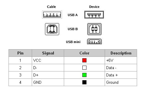
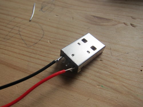
This plan needs two male USB A connectors (the “cable” type on the picture) to plug into the panels, and one female USB A (the “device” type) to provide the single output. Then female VCC pin is wired to both male VCC pins, and the GND pin similarly to the GND pins. The D-/D+ pins are not in use in this case.
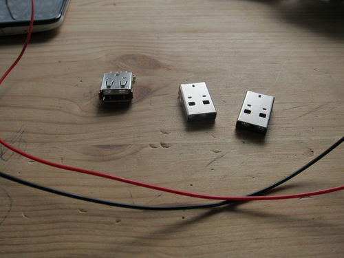
The connectors came in as $0.40 each, the wire I don’t remember but probably a few cents. I fortunately had both black and red to use with the GND and VCC. Things are better colour coded.
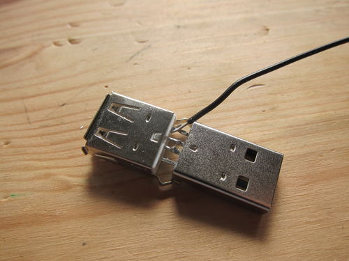
First the middle two pins of a male and a female connector is soldered together, just to provide mechanical support. The end of the cable is stripped and hooked around the touching pins (the GND pins on this picture). The two pins + wire is then soldered together, with enough solder to stay, but not that much that the other pins could touch.
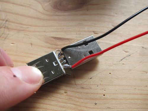
Did the same thing for the VCC pins + red wire. Finally added some more solder to the central pins. It was pretty stable like this, though I guess it would be better to have some sort of external housing for it or another way to increase the mechanical rigidity of the connection.
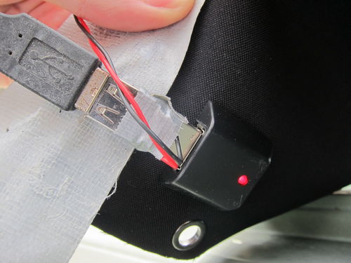
Finally the other connector is soldered, making sure that the right pins are connected (the same as the other male USB). The connectors are then wrapped in a bit of duck tape for some rough insulation. These parts will be outside, both in sun and rain, nothing much can break, but better not test whether I’m right about this particular point…
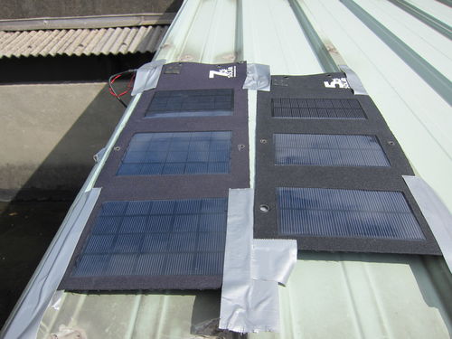
Plugged into the secondary (5W) solar panel, and into the primary (7W) one as well. Duck taped everything down onto the roof well enough that they are not blown away too easily (though I’d better check on them in a bit, the wind is howling just now outside).
As an aside, the duck tape doesn’t seem to like the sunshine. It sticks its sticky parts on everything, that part doesn’t seem to spell fun for the future.
Ready to charge
When everything is connected, the panels will get pretty good sunshine for the bigger part of the day. I don’t think they reach max capacity, because the angle is never ideal, but from the practical point of view, they get enough sunshine to max out the attached 2000mAh battery between device charges.
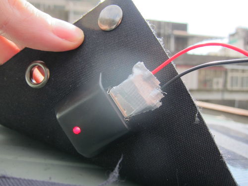
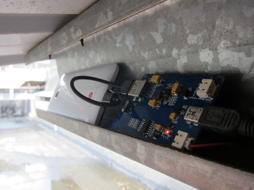
The Li-Po Rider Pro circuit is under the roof, so it doesn’t get any rain (at least I hope!), and has a little ledge to charge a phone safely as well.
Since all the devices were pretty much full when I checked in the Hackerspace after I finished this setup, the test whether combination of the two solar panels does indeed increase the power is not foolproof. Otherwise I would have charged a device from a low battery level to a bit higher with one panel, then later switch to two panels and see the different slope of the batter charge versus time. Normally at high charge levels (90%+) the slope is varied by the charging circuit (to preserve the lithium battery’s life), thus that level is not really good to test the difference between the single / dual panel situations.
One thing does suggest, though that the plan worked. Before this modification, charging a phone discharged the Li-Po Rider Pro’s own battery (there’s a touch switch on the circuit to get an approximate charge level, indicated by the lighting up of 0 to 4 LEDs on an LED bar), even in full sunshine. This time it seems that both the phone and the storage battery is charged up, indicating larger incoming power than before. I will check it again next time, though (the Nexus 7 tablet we have will be great for that, it has much larger internal battery than my HTC Butterfly phone)
Possible improvements
There are a few things I could improve on the setup, focusing on usability.
I hope to get a longer USB cable to reach from the roof to inside the Hackerspace, and set up a charging station within the room. This way people don’t have to keep their devices out of reach while charging, and there’s no chance of being ruined by a sudden rain.
I hope to get a larger capacity Li-Po battery. 5-10.000mAh could be good, then it would likely have enough power all the time to keep charging people’s devices, and not standing idle being full when not charging something, while easily emptied by a single device.
The roof also has plenty of more space, so getting a bunch of other panels, combined with the first two upgrades, would make it really beneficial. These foldable panels would be better portable, and keeping them in one place feels a sort of waste.
Ultimately it would be awesome if I could have a purely solar-powered phone. Because it would mean some money saved, but also, and mostly, because I can.