Nudged by a number of different news about bitcoin, I decided that this is the time to give it a new look and try to learn as much about it as possible. I wanted to explore how to use it in practice, so I have spent the last two days figuring out as many aspects of bitcoin as I had energy to do.
Introduction
As a short intro for those who are not familiar with bitcoin, check the “What is Bitcoin” video, or the Bitcoin Wiki. In a nutshell, it’s a kind of currency, that lives all in computer, based on cryptographic algorithms, in a way that people can send each other amounts of bitcoin securely. The coins are created by “mining” by computers doing heavy work, your balance is stored in a “wallet” as special numbers, and you send them from and to bitcoin “addresses” (people can have as many addresses as they want). The value of these coins decided by people exchanging it, between each other, or from bitcoin to currencies or back. (any thoughts on this introduction can be given in the comments, though I hope to explain things simpler instead of “completely” right)
Getting some
Since mining is out of practical reach now, logically there are two ways to get bitcoins: buy them, or earn them. Buying sounds more straightforward, and let’s check that one out first.
Exchanges
It’s much easier to say than to do to exchange any money to bitcoin. For seller’s safety (since there are not chargebacks in bitcoin, but on most money-exchange platforms there are), one has to jump through hoops to get anywhere. So far for me there were just too many hoops, no matter how much I was jumping.
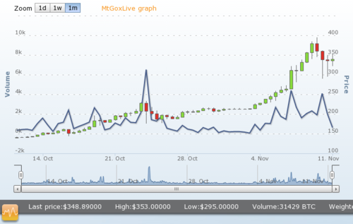
Mt.Gox is probably the most well known bitcoin exchange, based in Japan. I find it awesome that it was originally made to trade Magic: The Gathering gaming cards. A real effective pivot if I have ever seen one. The price is generally higher than on the other exchanges (better for sellers), requires verification to deposit, and as I read before, it has a history of suspending payouts when their cashflow is not good enough for it. I have started the verification just in case, hopefully their Japanese skills (ie. Kanji) help my Chinese language documents ahead. Don’t think I will use them to buy any coins, though.
Bitstamp seems to have somewhat lower prices (better for buyers), though the minimum deposit fee of $15 is pretty high. They also require verification though for me that didn’t work out: living in a Chinese writing country, even if my government ID has my address on it, and I typed in my Chinese address, they spit it back saying “we don’t read Chinese, get us a notarized English version”. That just doesn’t worth it.
Kraken seems to be another one that might work, since they seem to have a better connection to UK banks (will see in practice), and for historical reasons I still have an account in the UK with some pocket money that would be enough to experiment with. They seem to be the most lenient in verification, and pretty responsive support emails.
AsiaNextGen is a Hong Kong based exchange, and when I heard about it from a friend, I had high hopes, though in practice it didn’t quite work out. It could use Alipay to deposit as well, and just recently heard how popular Alipay is in China for all kinds of online trading. No wonder, since it’s a pre-paid account, making things more secure in an environment where both buyers and sellers have to be extremely wary of fraudsters. But that’s for another story. At the moment it’s enough that the English site of Alipay seems to be only for businesses, so that’s all for now.
If I ever wanted to start my own exchange, for a few minutes it looked like I had found the tool for that in the form of Buttercoin, an open source trading platform. But the software development seems to have stopped a few months ago. They also appear to be turned into a company called Buttercoin, which would be also interesting, though they don’t ship anything yet..
ATM
Learning more about the whole ecosystem, the bitcoin ATM seems to be an even better idea than an exchange. The relevant corners of the internet are full with the success story of the (not really) first bitcoin ATM in Vancouver. It just makes sense due to its convenience.
Robocoin is I think the maker of that ATM, and they look very full featured – as much as I can tell regulatory compliance from gibberish. They only seem to target Canada at the moment, maybe because it’s been tested and worked.
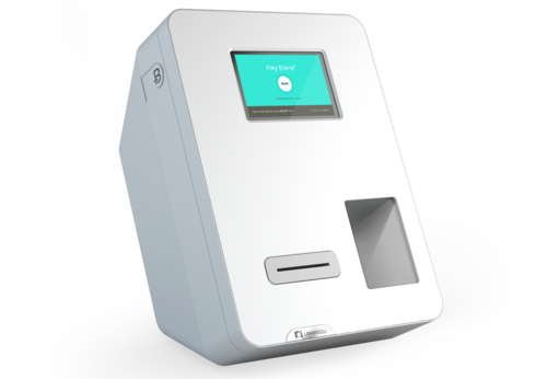
Lamassu is another vendor, that looks really good, and e.g. already capable of accepting TWD. If I had a spare $5000… The design looks really good as well, definitely would attract interest here.
It’s not an ATM, but close enough – LocalBitcoins would let people exchange BTC/cash in person. Except in Taiwan nobody sells (well, there’s one guy, but my spidey-senses are tingling about that listing).
Work for your bitcoin
If I cannot buy some, let’s see if I can earn some. Now this turned out to be a short, eye-opening journey to the underbelly of the Internet. Not too deep, I didn’t go too far, but I’ve seen more seedy websites than I’ve seen in a very long time. Won’t name names here, just to be on the safe side. :)
It all started with Google searches like “free bitcoins” and “earn bitcoins”, and there are enough sites for listing a lot of the services like that. The results are falling into three main categories:
- Sites that don’t work anymore (most “free” giveaway sites).
- Sites that have some kind of useful service.
- Scams
The most are I think 1 and 3, and there’s some overlap between 2 and 3 as what’s useful for the “worker” is not always useful for the community as a whole.
I’ve spent about 2 days exploring how these different sites work.
The most useful was an Amazon Mechanical Turk style service, where people can fulfill tasks requested by others. All are very low payout at the current exchange rate (you’d be lucky to make few $cents/hour with them), though some of them are lower than other. I had some kind of article categorizing, author discovery work that someone’s running, I guess scraping the web for personal and mental health topics. That had snapped up I think more than 20.000 tasks (each a bunch of sub-tasks) in a day or so. A better paying task is checking profile pictures of some social networking (I guess dating) website for policy violations. It paid better, but the tasks were quickly snapped up, and I’m kinda glad. That was enough of it.
Other sites seem to be focusing on advertisements, paying you to visit sites and watch videos. The sites are usually other bitcoin related services (trading, betting), though there were other ones as well, like investing in a poker playing team. The videos were mostly crappy pop music from performers who I guess couldn’t make it popular otherwise. Though most of these seem to come through a service which has a name suggesting they offer making your media go “viral”. Good riddance to both the sites and the videos, I don’t think I have seen more than a dozen sites and half a dozen videos (with the sound off:).
The last type of sites I’ve seen were for solving CAPTCHAs. Being a sysadmin who hates spammers, I didn’t use any of these. I’m experimenting, at the previous sites I actually did something (marginally) useful, and to my surprise I was somewhat interested in the links and videos I’ve seen that I would not have heard of otherwise. Deliberately hurting other sites, as I know these solutions would be used for, is not acceptable. Of course, this is just scratching the surface, and I don’t want to go that deep to see the “real” underbelly of the Internet.
All in all, this 2 days resulted in 0.00103601BTC ($0.36 at current exchange rate on Mt.Gox). That’s not enough even to send it to anyone free on the network (need a minimum of 0.01BTC as I know), but it’s some learning. I call it a day.
One more thing, I found a website where one could mine bitcoin using a Java applet, and turned out I did mine 0.08+BTC back in 2011. The site turned out to be a scam, though, so I think I can consider as those coins were never mine.
Practicalities
Besides the finances, I tried to explore the practical aspects of bitcoin as well, using it day-to-day, or how it could work on the long term based on my understanding. Most things are only as good as they are easy to use and reliable, those are my main questions in general.
Clients
I’ve started checking the different bitcoin clients that can create and manage my wallets.
Multibit was the first one I’ve checked, and I keep using at the moment. It’s really quick to start, and now it’s less confusing than it was 2 days ago. It’s easy to create new addresses, my notifications are clear, and can use multiple wallets. Will have to figure out how to export and import wallets to other services, though.
Electrum is very interesting, because it’s based on a pass phrase of a list of words, and algorithmically generates the follow up addresses. This two features make it easier to keep the wallet safe against self-harm (hard to lose). The client was too simplistic, and some of the things I didn’t understand, so went back to Multibit later.
The official bitcoin-qt client might be the one that does the heavy lifting for the whole network (and for the previous two clients as well, so they can be snappy). I was just horrified that it takes 14Gb of data (and almost one whole day of computation) to set it up. That data is the total transaction record of the bitcoin network. I cannot even think what will it be like when it will be truly popular. I’m experimenting with this a bit as well, though likely that in the future I’ll try to find another computer instead of my laptop to run this and stay with thin clients.
Blockchain.info is a very useful site, and could be great to start with bitcoin. I like that it has “watch-only” addresses (no spend just monitor), and their Android app can notify me when I got transactions to those addresses that I watch. It has a lot of geeky information and tools too.
There are a bunch of other ones as well, Brainwallet, Bitcoin Wallet, Coinbase, Bitaddress, and more. Need to digest all of this new information and come up with a good way how to manage and keep safe the coins.
Bitcoin itself
I’m learning more about the technical side of bitcoin as well. I feel I understand it more now that I’ve tried in in practice, and can as better questions.
The trickiest part I think is the issue of micropayments. At the moment they are discouraged because the technical architecture of things cannot really handle it. The earning services seem to handle it by grouping multiple payouts into a single transaction, once an hour or once a day. On the other hand, if I want to make a micropayment (or even regroup my tiny amounts into a single address), then I’d have to pay for it dearly.
These transaction fees are the other question, that it’s not that straightforward how much those fees are. Looks like too small, and too big payments both incur fees, but there’s a bit of arbitrariness about it, and I don’t quite understand it.
The long term changes to bitcoin, the transformation of miner incentives from mining payout to transaction fees make these even more critical, though it’s likely years till that becomes an issue.
QR codes are very widely used, I guess that’s the intersection of large availability of mobile apps and the need for accurately entering a very long string that is a bitcoin address. It seems to be a good idea, and one example I’ll use further down.
Overall experience
I’m really impressed by this first experience. There are a lot of issues ahead, but when it works, bitcoin does an awesome work. It is borderless so anyone can be paid very easily (good because more opportunities) and many people are striving to get a piece of the pie (not that good because the opportunities are quickly exhausted).
The technical side feels truly futuristic, and I feel much more enabled, and just a little bit scared by the “what haven’t I think of” when operating things. That user experience will surely be even better in the future. Merchant tools offered by different places (eg. on Mt.Gox) are also seem to be pretty good enablers (once people can actually freely exchange currency and BTC).
I’m also very impressed how many different services people created based on bitcoin. There are truly awesome services, and also a lot more “also runs” who are still clearly more than a minimum-viable-product. If so many people are creating so many things, I am thinking why does it take so long for me to get my own (much smaller) project going?
Now let’s see what does the future bring. I hope I can contribute to this as well in some useful way.
 If you like the blog, bitcoin, and want to experiment, you can throw some bitcoin at me at 1Pem9zU7AMMif4t6zyP6r84T2BaEsY6USg. All donation I will use for good, among others to support the Taipei Hackerspace (there’s a direct donation link on their website as well).