I use Google Meet every day for (potentially hours of) online meetings at work, so it’s very easy to notice when things change and for example new features are available. Recently I’ve found a new “Call Control” section in the settings that promised a lot of fun, connecting USB devices to control my calls.

As someone who enjoys (or drawn to, or sort-of obscessed with) hacking on hardware, this was a nice call of action: let’s cobble together a custom USB button that can do some kind of call control1: say muting myself in the call, showing mute status, hanging up, etc.
This kicked off such a deep rabbit hole that I barely made it back up to the top, but one that seeded a crazy amount of future opportunities.
And as a shortcut, there’s a demo below to showcase where I got to.
Finding suitable hardware
This step was harder than I’ve expected, given that I have drawers and drawers of gadgets, but I’m likely a bit out of practice, and also out of date. What I was looking for is
- Being able to show up as a USB device (must)
- Have built in button (optional) or easy connectivity of buttons without breadboard for now
- Have built in LED (optional) or some other way of showing 1 bit of information
This doesn’t sound hard, right?
ReSpeaker
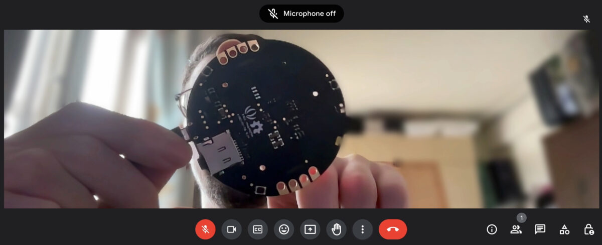
The first option that came up was Seeed Studio’s ReSpeaker Core that I had two of at hand: Arduino Leonardo compatibility, touch sensors for buttons, and an LED ring (the “Pixel Ring”). Turns out that they have been discontinued – which should be fine for now; but also my models are two different pre-release prototypes Seeed gave away for testers. Thus they are not quite like the final version, have different hardware on board here and there, so an experimental experience is expected.

The earlier prototype only has touch sensors on one side, the pixel ring lights up, but I couldn’t control it with Seeed’s ReSpeaker Arduino library. The later prototype has two sides of sensors (effectively two buttons), but the lights don’t seem to work2. Regardless this
Aside: alternatives considered
It was illuminating to see how much abandoned, obsolete, discontinued, or not quite useful hardware boards do I have.
One is RFDuino, that I got from Kickstarter, I’m yet to use, and all the project’s websites have already disappeared – fortunately not the code repo. This would have been a more complex solution anyways, but wireless! Use one RFDuino to expose a USB Telephony device, and communicate wirelessly to another that operates the light and button on battery. Pretty cool. Also, it might not have worked if the chip used cannot do the cruicial “expose a USB [device]” part of the plan.
Other option that popped up was an Arduino Nano + my own made GroveHat + a Grove Button. Except, the Nano definitely cannot be a custom USB device, so there goes nothing.
Besides these, I’ve found plenty of:
- single board computers (old or obsolete),
- FPGAs (never used, and would be a whole different project to implement something on them), and
- other microcontrollers that all have interesting specialties, but don’t tick the mandatory boxes…
These boards might not be right for now, but definitely there are projects in store for them (if only thre’s time).
Back to ReSpeaker then…
Plugging in the USB
The next thing is to figure out what’s really happening when an USB device is plugged in and it shows the operating system that it can do certain things. That is, how does Meet know that there’s a compatible device to connect to?
The USB HID docs
This is answered by the USB Human Interface Devices (HID) specs — one that is pretty complicated, has a lot of legacy bits, and need a different kind of mindset. In a nutshell, though, with my current, partial understanding:
On connection the device sends a “report” to the OS that details on what can it do, including:
- what kind (or kinds!) of device it is?
- what functionality of the kind is available in this particular implementation?
- what’s the data layout to pass control information back-and-forth for this implementation?
In our example, a very minimal setup would would be:
- I’m a Telephony Device (Usage page
0x0B) - I implement a generic “Phone” (Usage ID
0x01) - I have capability to do a “Phone Mute” (Usage ID
0x2F) - Here’s the 1 bit of a 1 byte payload that conveys that phone mute status

This course does not take into account other functionality, e.g.
- I can also hang up – Hook Switch, Usage ID
0x20; - I have status LEDs – that’s a whole fun of redefining functions on the LED Page
0x08;
and so on. But for the time being this should be enough.

Device implementation
Fortunately we can stand on the shoulders of giants, that is the Arduino HID Project which implemented a bunch of different devices. And even though a “phone” like this is not among them, we can make some reasonable guesses how it would work.
Having said that, from a forum post that was also trying to do something similar (but based on the TinyUSB library):
HID report descriptor is very difficult thing to come up by oneself. You should google around, or dump report descriptor from existing device to copy/follow it.
hathach @ TinyUSB discussion 667
Okay, then do not come up with this stuff, instead let’s look for tools. The USB HID homepage links to the Microsoft HID Tools to generate HID reports from a TOML-like language. Except it needs C# and I just wasn’t ready to dive in a side-quest to install & learn a new toolchain.
So being lazy this way, a bit more sleuthing turned up someone’s example HID report for a device very close to what I’m trying to do, hurray!
I took this and started to poke around the HID project to see how other devices are implemented. Troubleshooting by using the ReSpeaker’s touch to adjust screen brightness up / down (as a “Consumer Device”) was also pretty neat! In the end I took the system buttons example and run with that one.
Having said that, the HID report is really just the interface. The devil is in how to implement actually creating the data packages that passes data according to the report definition. And this is the case when I wish I knew more C++ but copy-paste and some guesswork will have to do.

The current result lives in the “phone” branch of my HID Project fork, check for the “Phone” bits in “src/HID-APIs” and “MultiReport” folders, if interested.
Minimal viable mute
The implementation from this point on was pretty straightforward – since we cut back the scope so much…
The code to run on the ReSpeaker then just has to do the following:
- when touching one side, send a report with “Phone Mute” on
- when touching the other, send a report with “Phone Mute” off
And this is sort of simple3 :
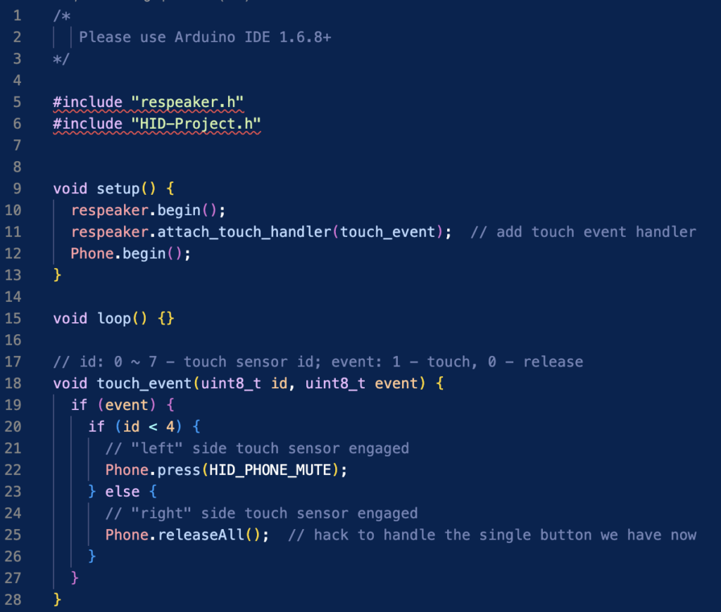
For the full use case there would be a lot more complexity for both reading and writing data from the host, controlling multiple peripherals (LEDs and buttons) and the whole logic around it. But for now, it’s good enough for a demo:
The code repository is available on Github at imrehg/arduino-usb-phone-hid.
Notes and Future work
The specs
It’s great that stuff from 20+ years ago still works mostly the same way. The latest 1.4 version of the HID Tables is nicely formatted, has a lot more device typed defined, but has much less support text. Originally I’ve read the 1.12v2 version as that showed up in my search. Back then in 2004 they had an “examples” section (see the Telephone at Appendix 10!) which is useful to grok more of the fundamentals.
The newer version also has some devices types that looked suitable, but weren’t really: Generic Desktop Page (0x01) and 0xE0-E2 Usage IDs for Call Active LED, Call Mute Toggle, and Call Mute LED respectively. These didn’t seem to work with Meet, so it might be interesting to try implementing a device that does both and try other online call software.
I should also have read the spec more before diving into hacking on the HID implementation fork, as there’s a lot more information in the HID Device Class Definition, including how to construct the values for many of the fields (I’m looking at you “INPUT (Cnst,Var,Abs)“). RTFM is and remains a solid advice – and not just when one thinks there’s time.
Also regarding the specs: some of them I only find in the Internet Archive’s Wayback Machine. If you encounter a good source that should be kept, always add it to the Wayback Machine and preserve it for your future selves and others!
This exploration of USB HID pulled on so many threads, and left so much unfinished, that it’s a fertile ground for the future, even more than most previous projects.
More call functionality
The most obvious thing is to implement the whole setup with the buttons. I’ve tried Hook Switch to hang up a call, that works too. Could add status lights, maybe throw in some “Active Call” LEDs, or so on. This requires better understanding how data is sent over the wire for USB and how to handle incoming data. The Arduino examples rarely seem to use the “Output” fields (ie. incoming data, output from the host’s point of view, but maybe TinyUSB does ?
For this, it would be nice to find a different hardware platform that would make this more seamless (so I can concentrate on the software side more). If that platform would lend itself to be reproduced or made stand alone, that would be even nicer: imaging brining my little call control box that can be used with other computers easily as well…
Implement more USB HID devices
The Arduino HID project has a bunch of devices implemented, but there are an infinite numbers that could be added. Unfortunately for Arduino it is harder to add more device types as an add-on to this library versus the current “forked” approach4, so new decices should be in the main project, eventually.
So far there’s no Telephony device implemented there and it would be nice to find the right level of abstraction that works. The library doesn’t implement specific HID table pages, but specific usages or a subset of a usage. Thus like always, the hardest part would likely be setting the right interface (the right specs and “API”) for a new device to implement both the HID reports and the functions that manipulate what’s being sent and when.
On the other hand, that does sound like a fun experiment, and I’d look forward to adding 3D Game Controllers (Game Controls Page 0x05), Environmental Sensors (Sensors Page 0x20, Usage ID 0x30-3B), … or even a Submarine Simulation Device (Simulation Device page 0x02, usage id 0x05). These are stuff I go to Hackerspaces for…
WebHID for internet plus USB
While debugging this HID device behaviour, I found also WebHID that brings such devices to the web. This feature seems to be behind Meet’s and other phone systems like 3CX expanding USB support outside of the OS and into the browser. And no, Firefox does not support it, furthermore declined supporting it.
Nonetheless it’s very cool that (if I upskill a bit), I can create a web page that would help me debug such HID development:
- request devices that are filtered in various ways (vendor, product is standard, but usage page and explicit usage is the main key). This is likely what Meet does as well, “just gimme devices with Telephony usage page (or Phone usage? Need to check exactly)
- read the HID report collections sent by the device, so the results can be debugged, and
- read device input events that we can then either log for debugging or in an application react to to it
This opens a lot more mashup opportunities by the dozen.
Finally
Unlike most other projects I had where I’m focused on one specific outcome, this turned out to be more focusing on getting a new toolkit (custom USB devices) up and running, so I can think about a wider types of projects to do. In that sense, this feels a big success, even if I know how little I know about programming outside of my day-to-day environment. But ignorance is not a bliss.
And now, going on mute.
- Many moons past I used to use a Jabra Evolve 80, that has a USB accessory controlling call features, so I did have first hand example of what sort of experience I’d like. ↩︎
- I’ve tried reviewing the hardware schematics, looking into the pixel ring control functions, and given that the LEDs seems standard I’ve also attempted to use the FastLED library to drive them instead, so far nothing. I still bet on hardware differences from final schematic + my inability to debug it, but it can be faulty hardware just as well. Needs more effort – in the future. ↩︎
- The Arduino code became more “simple” once I realised that things set up this way do not need debouncing for the touch sensors. In other cases that would be essential, there’s sooo much flaky signal to use those terminals as momentary switches or similar. ↩︎
- At least I don’t know how nicely extend a library for C++, if that’s even possible. Keen to learn, though. ↩︎
2 replies on “Making a USB Mute Button for Online Meetings”
hey, this is super cool. I am trying to port it over to circuitpython but am running into some isues that I think are answered in a few of the dead images on this post.
this is what my raw reports look like
“` sudo usbhid-dump -s 01:121 -f -e stream
Starting dumping interrupt transfer stream
with 1 minute timeout.
001:121:003:STREAM 1716148768.278185
0B 2F“
google meet sees the device and connects, but does not mute or hang up.
Can you share what your raw reports look like?
I’m in the same boat trying to recreate this – Meet enumerates and connects to the device, but does not respond to the input report (assuming the input report is in fact being sent).
Anything more you can share would be very helpful