Just a bit more than a year ago I’ve started to work on a hardware idea as a challenge – a mini-PCIe form factor Arduino clone, the PCIeDuino. The inspiration was working with a bunch of embedded boards, especially the VIA VAB-600 Springboard, that had a mini-PCIe connector, but not that many accessories that can go in there. (Disclaimer, I work at VIA at the moment, though this wasn’t a work project). I thought it would be cool to put an embedded-grade microcontroller on these boards, mostly to expand the I/O capabilities.
Idea
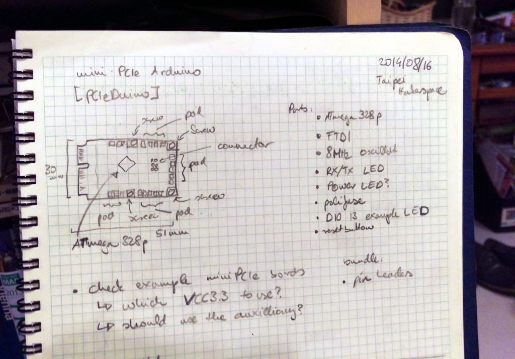
Looking at the mini-PCIe specs, the connector has mandatory USB 2.0 lines so communication was solved. The area available, roughly 5.1 x 3.0 cm, is not too bad -more than how big the Arduino Nano is in comparison. The biggest challenge probably was that there are only 3.3V power lines available, and most example designs use 5V power supply.
Fortunately Arduino is released under quite permissive Creative Commons CC-BY-SA license, which means whoever makes an Arduino clone, also has to release it under the same license. This gave a lot of interesting designs to scout and learn from.
The original plan was using a similar Bill of Materials as the Nano, based around the ATmega328P, but two things happened to change it. First, I’ve changed my mind that I didn’t want to use the FTDI FT232 chip they used for USB-to-UART conversion. Second, my clever electronics friend Niko figured out that the tiny bit more advanced ATmega32U4 microcontroller would also work at 3.3V and since it speaks USB natively, could cut a bunch of components (that’s always good). The trade-off is a bit of clock speed (running at 8MHz), but that’s acceptable.
Design
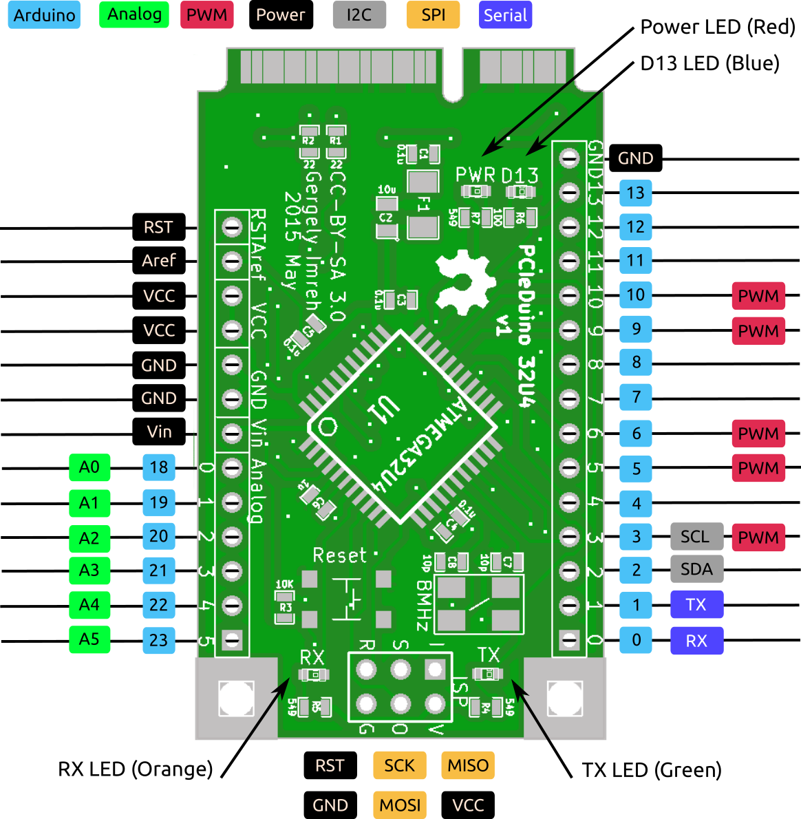
I did find clone with these parameters (3.3V power and ATmega32U4), the SparkFun Pro Micro 3.3V. Took that basic design, replaced some components, added a Power LED, and broke out the pins differently. Done in KiCad, the result is this PCIeDuino design below (or check the PDF version).

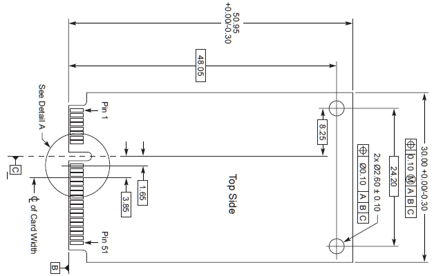
The next step was fitting all these components onto a mini-PCIe card. The board size was sketched in detail in the specs, though somehow all the dimensions were described in a way that it was quite inconvenient for making a board outline. Nothing that an hour of math cannot fix…
Actually, had to do the board layout twice, because for the first prototype (that I actually got printed) somehow had a crystal footprint that doesn’t correspond to any available 8Mhz crystal that I needed – so had to start again a bit. I took that chance to reorganize the board bit, and that extra round of design did a lot of good to the quality! More logical layout, better component grouping, simplified arrangement.
The biggest challenge at this stage was wiring the output pins. That part was done with a few tries of autorouting with FreeRouting. The idea being that it’s a low frequency, small board so likely not too demanding design-wise, and getting it printed is more important that fine-tuning it to death. The USB line was hand-matched, though, and the LEDs were arranged to face the same way for easier mounting, so not all just auto-optimize.
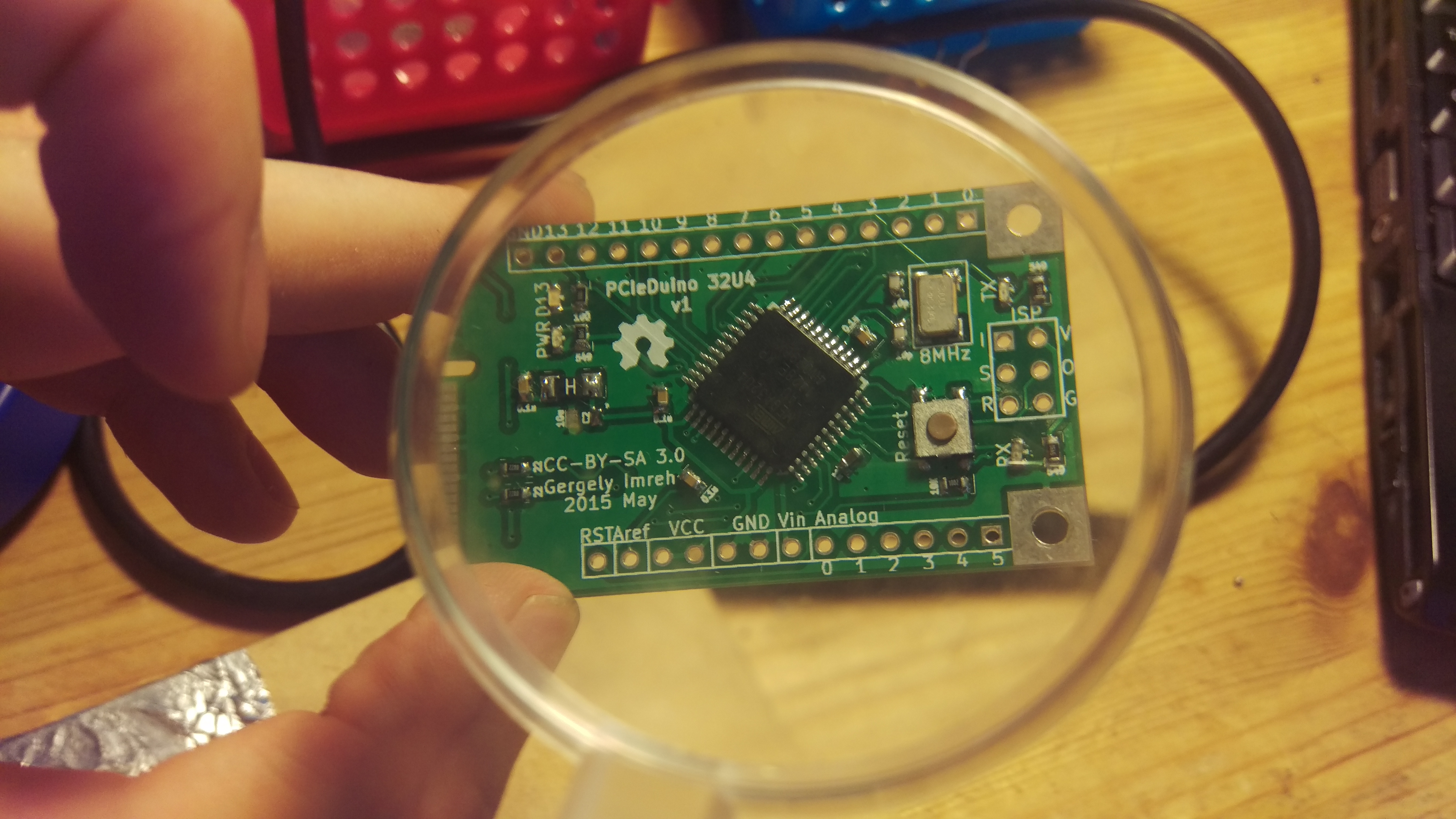
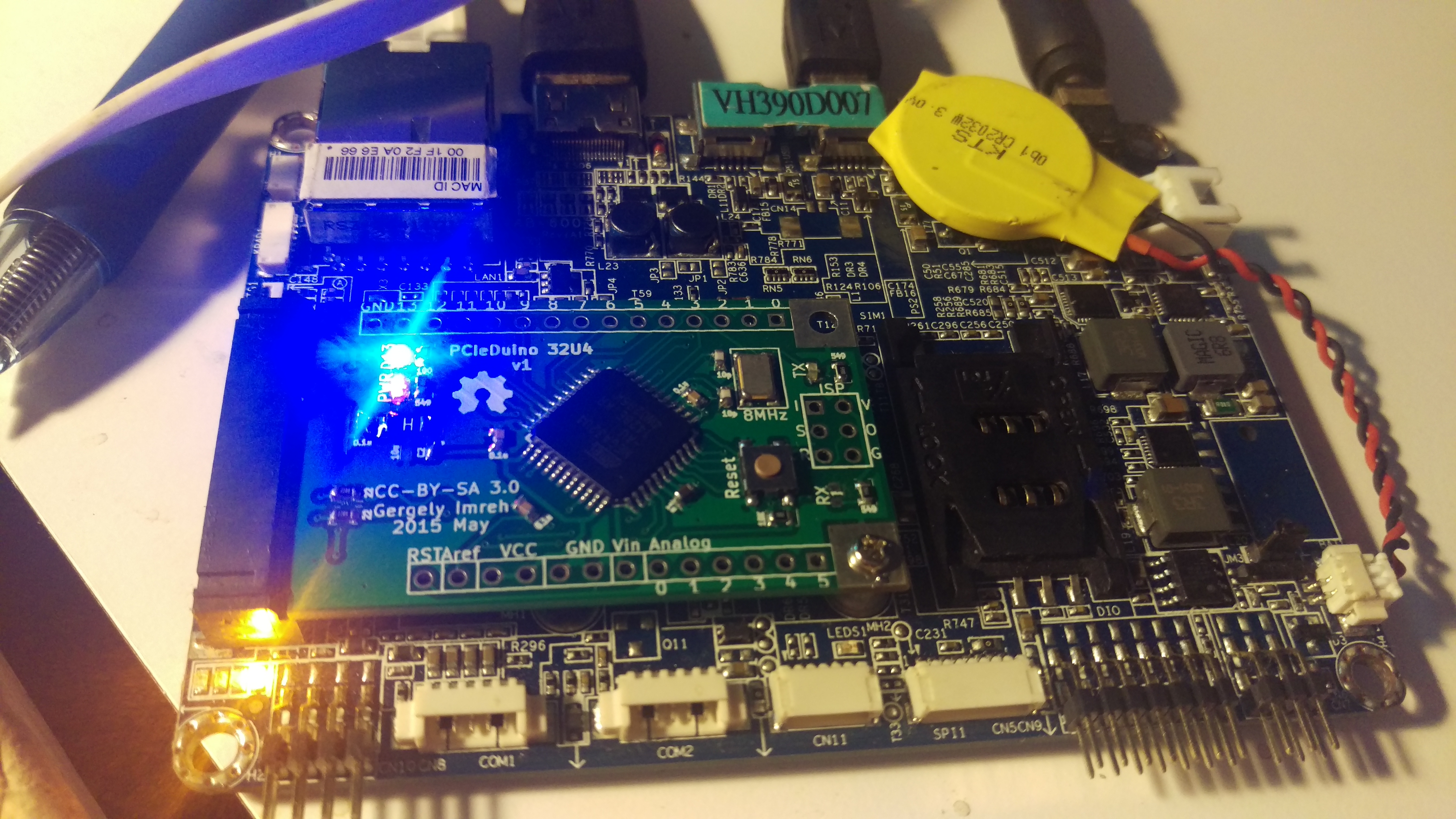
The tape-out happened in May, about 9 months after getting started (and about 4 months downtime in between). The resulting board looks like this:
I’ve submitted the board to Seeed Studio’s Fusion PCB service, and got it back in about 2 weeks. In the meantime the components were ordered from Mouser, the parts for 10 boards (equal to the number of PCBs printed) just being above the minimum threshold for free shipping.
Alive
Then came the assembly – hand soldered surface mount components can be really frustrating, but I really got to like them by now. If only my left hand was better (I’m right handed – solder in right hand, tweezers supposed to be in left). The assembly took about 1 hour altogether.
Now it’s time for waking the board up. Fortunately SparkFun’s Pro Micro firmware fits nicely onto the PCIeDuino too. Using an USBTinyISP clone (from eBay), a bunch of pogo pins, and the ISP headers on the board I could flash the firmware.
Plug it into the the embedded board and powering up, the blinking D13 LED showed that everything should be pretty close to alright!
Since then I’ve assembled altogether 7 of the boards (still takes about 1 hour each by hand, but I’m getting better). Had a few failures, but now I also know how to diagnose those issues better.
(If curious, so far had “magic smoke”, cold joint, shorted microcontroller pins, and now a board with a short somewhere that triggered the fuse. Ah, the learning!)
Advanced
Now the PCIeDuino is available on Tindie (whenever I have a bit of time to assemble more). It a great experience trying to make a compelling maker project that other people want to use too! Having better documentation, more explanation, better software, better communication, and actually going out finding people who are interested in this could be pretty much full time work!
I got my first Hackaday feature too, not that it was a great article, but the discussion was very illuminating and helped me to polish my own idea regarding this project.
All the KiCAd source and Gerber files are available on Github with CC-BY-SA license, so others can take this design to places too!
Future
The PCIeDuino is still very much a prototype project, more suitable probably for advanced users who are not put off when not every path is well worn out. I have to test it a lot more too, and find interesting use cases!
It looks like that the SparkFun firmware is not very well maintained, and it could be useful to look for alternatives. Optiboot seems to be interesting, but it also needs some work for the ATmega32U4 chip. Software support is super important, though, so this got to be a high priority improvement.
The original idea was to use this on embedded boards, that are mostly ARM systems. It should also be easy to use, Arduino IDE compatible project. The problem is, that the two parts are at odds with each other. The Arduino IDE doesn’t quite work well on ARM yet, so it’s mostly command line operation at the moment. Not a breaking change, but still a fail that needs to be remedied somehow.
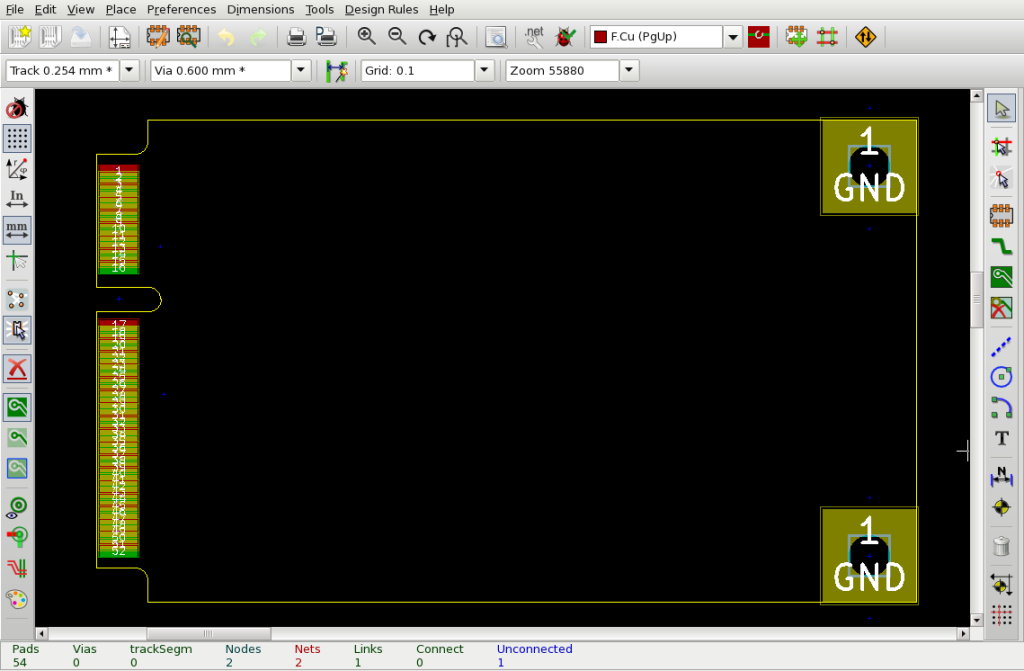
The board is designed to conform to the mini-PCIe board specs. It fulfills the full-sized board variation’s requirements: the board outline, 1.0mm PCB thickness, connector pins, mounting, keep out zones, …. It does not do the beveled cut at the connector (45º bevel cut needed, but seems to work regardless). To help other people to design mini-PCIe boards, I’ve put together a bare board starter kit in KiCad, available on Github, which includes the connector schematic, board outline, pin placement, and top-end mounting holes. Would be good to make a half-sized board variation design as well in the future, though at the moment it’s not a priority (pull requests welcome!)
This project also gave me a lot of ideas for future devices: similar mini-PCIe designs with ATXmega or ARM Cortex-M microcontrollers, and other Arduino clones with special functionality, e.g. built around the ATmega2564RF2 for 802.15.4 mesh networking… But first, take this design to its full potential…
If you like this idea, check out the PCIeDuino on Tindie, and would love to hear any kind of feedback or comment too! There’s a lot to improve, even if this is really the most complex electronics design I made so far… Now back to the drawing board and to soldering!
5 replies on “My first non-trivial hardware: PCIeDuino”
[…] is really my most complex project yet, and I think it’s finally close enough to a “real” hardware to offer very […]
[…] rozhraní, které jsou v běžných mikrokontrolérech (USB, I2C/SMB) jak ukázal skvělý projekt PCIeDuino – mimochodem layout desky jsem převzal právě z PCIeDina – many thanks Gergley for […]
Hey can you please share the footprint of the mini pcie edge connector on github.
Hey, this project is pretty damn old, and encountered a lot of “bit rot” – libraries, footprints are missing, so cannot really use it myself either. Would recommend reimplementing it from scratch from the specs, just like I did, it’s not super difficult (as I recall…)
[…] also a lot more hardware design projects than before (but still fewer than I wanted), including the PCIeDuino that still has a lot of unrealized potential; for writing there’s the Atomic Physics […]