After holding out for years, just recently made up my mind to buy a 3D printer. Before all the “affordable” models were US$2000+ or so, and even if I was really interested in them, I couldn’t make up my mind about such a big expenditure. The factors that changed my mind recently were: hearing about Portabee, a sub-US$500 printer (that is as a kit); all the interesting things happening at Taipei Hackerspace where I wanted us to have an interesting new tool; and having acquired a brand new credit card (oops).
I ordered it in the beginning of may, from a Singaporean store called Romscraj, that seems to be somewhat affiliated with the original makers of the printer, and had better rate for shipping over here to Taiwan. (At the time of this writing, the store’s website is redirecting to a static image, though, I wonder what’s up).
The package had 3 weeks lead time. Now, having tried how long does it take to make a single print, and seeing how many self-printed parts the kit has, I’m much less surprised about that. The DHL delivery was pretty darn quick afterwards, apparently it helps to have a distribution centre over here.
Then one fine Friday noon about two weeks ago I got to open the box and unpack.
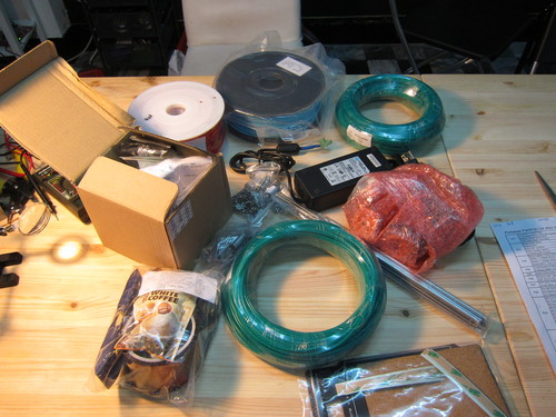
Little packages for the different screw sizes (M3/M4/M5 and their nuts and washers), the electronics neatly packed, metal pieces that looked sturdy at first, the heated bed for the print, a bunch of tool, spools of printing materials (I ordered a few extra spools, one can never know).
I liked the included instant coffee, that felt like a nice touch, and that there were enough tools included for about 90% of the tasks I encountered later (for the screws, leveling mainly, that’s what a 3D printer assembly is mostly).
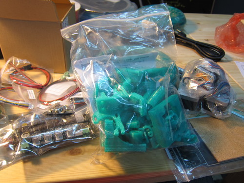
There was of course the big bag of printed parts, in nice green (still like that colour a lot, though the original website’s red prints are not bad either). Big bunch motors (or let’s count them: 5), and more electronics. It all made a happy pile, and I have also started to appreciate the task ahead of me.
I brought up their assembly manual on the screen, turned on some DJ Krush, and got to it.
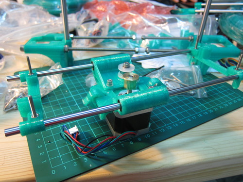
Since this supposed to be a portable printer (the name alluded to that already), it has somewhat different design than the other ones I’ve seen.
Starting off with the base, it has already some fun alignment tasks and screw tightening. The latter is almost like an art: how much you tighten that you don’t break the (not totally, but still plenty) fragile plastic, but don’t let it loosen by itself either. This is something I’m still learning and I am convinced that it comes from experience, from the problems one finds doing it one way or another.
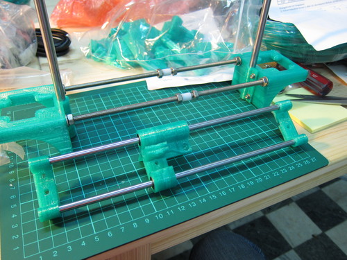
So far so good, making the base, then starting on the horizontal bars, and more motor mounts. All X, Y, and Z directions had these switches that would tell the controller that “please don’t come closer” and lets the machine find its home easily, and (more importantly) quite safely. The first puzzle I hit was that these switch circuits were soldered in a mirror arrangement, compared to the manual and instructions. The circuit board apparently lends itself to both directions, still it is mighty confusing. I wrote an email to the store I got my kit from, and they just told me what I have found in the manual later, that these switches can indeed be made in either direction.
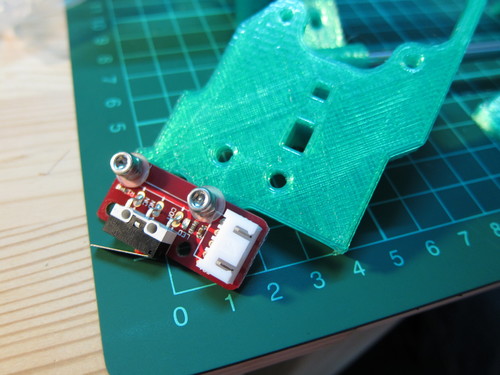
Not a big deal in the end, though I had to change a few things around and mount them differently. When the white connector is not in the way in the original design, it can be very much in the mirrored one if I don’t move it somewhere else. It was especially a problem with the X-movement (the table back and forth). Just a bit of awareness and adjustment is fine.
Got to some of the motors already. There were two different types, one with the cogs on top (2 pieces), and another without (the other 3). So far so good, those are easy to distinguish. On the other hand, I should have read the manual better (first mistake), or actually took a look at the motors (compounded mistake), in either case I would have been certain which one goes where. As it was, I kinda guessed, and while the guess worked out relatively fine, I just had to exchange one pair of motors in the end (because of the insufficient length of cabling for one). Just a bit of extra assembly in that case, but could have been worse if I had to exchange other ones.
Some of the rods were actually slightly differently sized as in the manual, and it was hard to see sometimes when they were insisting accurate measurements of some parts, down to a millimeter, that how things are going to fit together further along the assembly. For example the “250mm rod” I received was more like 265, thus they didn’t really put the kit together to the same accuracy as the original design.
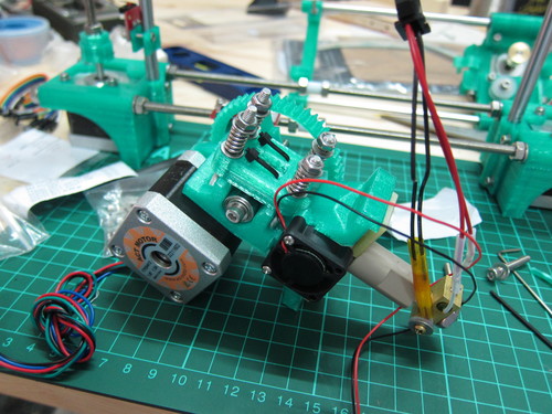
The extruder head had its own separate manual, and I’m not surprised. The most sensitive part of the whole thing, but all in all it is not too bad. The manual in general does a good job, but in this case I did find some deficiencies in their graphics, not really knowing where to lead the cables for a good assembly. The cooling fan had a funny case of being oriented by the location of its sticker – while the one I had didn’t have such a sticker really, so I had to guess a bit which way does its wind blow (spoiler: I was wrong, had to reverse it later).
Mounting it all on the top it starts to feel more solid and sturdy. Had some funs trying to insert the printing material first in the alignment stage, I am sure it gets easier in practice.
For the rest of the parts I had to find a good file (the tool “file”) to make some of the holes larger, where the printing was too tight. The tool street is just next to the Hackerspace, though, so it wasn’t a big deal and was back in business in no time. Still the tight parts ment that once some of them were on, there wasn’t really any way to take them off, short of braking them.
In the end, after about 10 hours of assembly (distributed in two days), I got the whole thing up. When I realized that it took this much, the ~US$150 extra for an assembled kit starts to look much more attractive. Still, I like that I did it myself, because now when it breaks (as it so does it will break a lot) I will know more or less what to fix.
After the hardware setup and testing, had to figure out the software to breathe some life into it. Given that I’m a Linux user, maybe I should have done it earlier, preferably before actually ordering it, otherwise I’ll end up the same way as I did with Galago – having a tool but not having a way to use it.
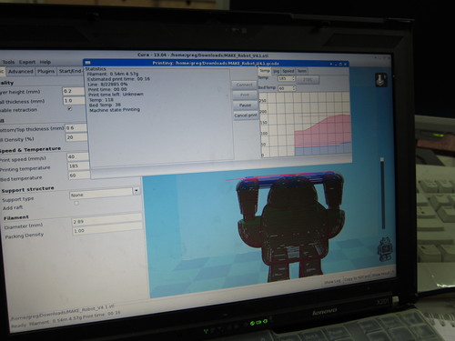
Fortunately the manual was very helpful, and pointed me to Cura and Pronterface to use. Strangely, Cura didn’t install well onto the Hackerspace’s Xubuntu, but it worked pretty darn well on my laptop’s ArchLinux, so used that afterwards.
One part of the software control that should put people on the edge at first for sure (and probably for a while) that it’s actually a pretty high temperature tool. The base is around 60°C, the printhead goes up to 185-225°C (depending on the material). The fan on the extruder supposed to be very important, and that can only be enabled manually in Pronterface, by sending the command “M106” to the printer. It can be tricky since sometimes the printer has to be plugged in and out to respond to commands again if I switch programs, and that would make the fan not run for a while. Might not be a big problem, but will not know until something breaks.
Another problem is the temperature stability, and in the safety point of view, even before the print quality is taken into account. The temperature is stabilized by feeding back a temperature measurement of some glass bead thermistors. So far so good, that’s similar thing to all the other temperature stabilization I had in the laser physics labs before. The part that you don’t want, though, is to have the thermistor separated from the thing it measures. Then the heating would just go up and up, since the electronics thinks it is not hot enough, while it just measures the air somewhere else. Not the mother of thermal runaways, but would still make me a sad bunny.
The thermistor here is mounted like on this picture, with a piece of silicon washer behind the brass screw.
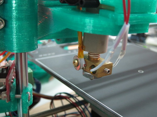
The problem is that as soon as I try to secure the thing with the screw, the turning almost inevitably throws the bead out. Even when it stays in, the increased temperature popped it out a few times that I had to initiate an emergency shut-down.
The screw hole is actually a through hole, so if I can figure out a good thermal contact inside, it would worth dropping a screw altogether and run the bead through the whole the next time.
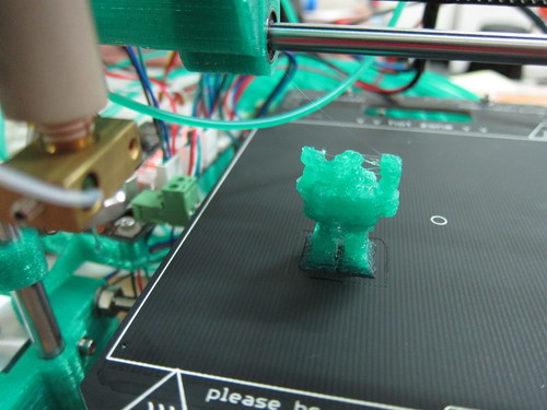
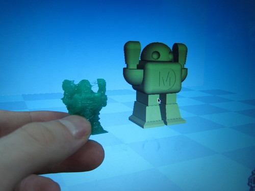
Now, ready to print, try it first with a relatively simple model, a Make robot. Takes a few minutes to heat up and stabilize the temperature, but it’s pretty automatic.
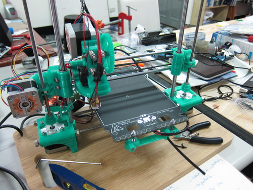
Everything is prepared, and even if it’s a bit of a mess, it made sense. Got a nice heavy flat wooden chopping block as a base. Looks pretty flat and almost 2cm thick, should be sturdy enough. It is also from the neighbouring tool street, there’s a pretty good kitchenware store I frequent.
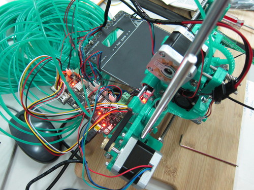
After the heating up time, everything kicks off pretty quickly. The head runs over to the middle of the board and start laying down the structure. I was actually quite surprised that it worked for the first time, but that’s just my own (non-) trust of assembling abilities. The structure felt relatively sturdy, with the exception of one of the Z-screws that lifts and lowers the head is wobbling visibly, though so far I cannot see how much effect that will have on the print quality (might need to take that one out and balance it back again.
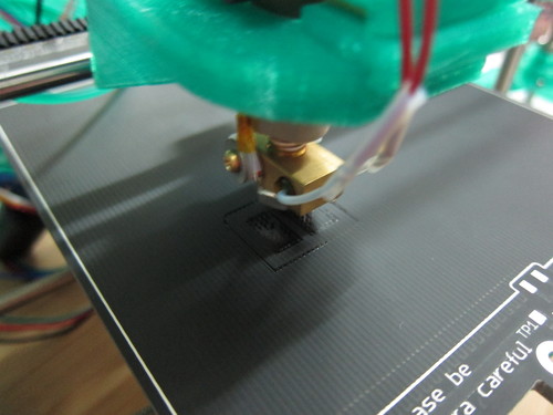
Well, the first finished piece is nothing to be really proud of. I actually rescaled it to 50% so it finished quicker, and also I wasn’t sure how high I could print. It is a total mess but still kinda recognizable.
No problem, however, this just means that I will have to adjust the parameters of the printer to find the right values for half a dozen to a dozen variables. Head traveling speed while printing and while not, pullback distance and pullback speed, flow rate, head temperature, these sort of things. Looking at the default settings in Cura is not really helpful, on the contrary, they are for a well calibrated Ultimaker, that feels more sturdy, eg. the recommended printing speed is almost 4 times the one in the Portabee wiki. Some experimenting times ahead.
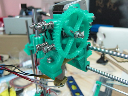
Or actually it would have been experimenting times ahead, if a few hours later I haven’t had broken the printer. The main extruder motor’s cogwheel was pretty much shaved clean by the large cogwheel, thus disabling the whole extruder. This is not that much of a surprise upon closer inspection: while the large cogwheel is totally solid, the small one’s cogs are just one layer of “plastic wiggle”, barely touching the actual cog centre. I will have to print a new one, most likely making the design sturdier, and maybe even printing it in a different material.
Also, the clips that hold the table on the horizontal bars broke too, too think for the pressure they had to endure by the clipping. That needs some better solution as well.
For the time being, the printer is taking a rest, and I can reflect on “so what have we learned“.
Lessons learned
If I were to order a bunch of 3D printers, maybe I would get an assembled version. In Portabee’s case, the difference is about $150, which divided by the 10 hours of assembly time is not a bad deal. On the other hand, in retrospect the assembly was interesting and definitely required exercise to be able to fix whatever goes wrong. And feels more like the “hackerspace way”, if there’s such a thing.
It felt like as if some of the design choices were mere wishful thinking, and don’t work that well, even if at first look they are pretty clever. For example many of the hex nuts are held in place by depressions in the shape of the nut. It works well for M4 and larger, for M3 it works “usually”, and I wouldn’t really rely on it, unless the printer doing the piece is very well set up. Same verdict of “so-so” for the heater block thermistor’s assembly, the print table’s clip on, the electronics board holder. There are plenty to learn though about mechanical design through the choices, like the Z-lift screws, the translation belts, some of the smaller stuff.
Maybe the biggest lesson is to read the manual beforehand. I remember one of my friends actually asking me when I have started, “Greg, have you read the manual?” “Oh, I’ll just follow it up as I go along” was my line back (more or less). Not a good idea. No matter how good the manual looks, there are always non-obvious differences that had to be fixed, and unless one knows the outcome, it’s hard to make the required trade-offs.
I have tried some prints I got off Thingiverse while the machine was still working, and it seems to me that many of them don’t work well when rescaled, while they still should. Feels like I want to get out some 3D modeling software and make some alternate designs, filling some holes here, making things sturdier there. Google Sketchup is the most popular one I keep hearing about, though that does not really work for me in Linux. Fortunately I found that FreeCAD, that I have used for other projects and wanted to find more use for as well, can very nicely prepare the required files as well. And it’s scripted in Python, paving the way for some algorithmic design ideas.
5 replies on “Assembling my first 3D printer”
Cool writeup, thank you for making it available.
I had a similar experience with building a Printrbot, albeit with laser cut plywood instead of 3D printed parts.
Building the kit was worth the experience, never mind the fact that the kit was junk. Understanding their perspective and implementation of linear motion was key, as was putting together a somewhat functioning hot end.
Having said that, today I would much have rather purchased a turnkey Makerbot or Lulzbot with support.
Cheers
Thanks for the feedback, I was actually thinking about Printrbot this morning, because I felt the lasercut plywood might be more stable than the 3D printed parts. Glad that my instinct has stopped me short. :)
I am quite excited about people trying to make something reliable and usable out of the box, for example I was checking OpenBeam Kossel Pro recently http://www.kickstarter.com/projects/ttstam/openbeam-kossel-pro-a-new-type-of-3d-printer . I just cannot really justify US$1000+ on these things at the moment.
Are considering getting any other in the near future?
OpenBeams are pretty cool, I have a set of them here from Adafruit. V-Slots look very promising for linear motion systems as well:
http://www.kickstarter.com/projects/openrail/openbuilds-v-slot
Based on my issues with Printrbot I am probably going to go with a Mendelmax 1.5+ build next.
Excellent write-up!
It looks like some of your stringing/melting problems are from making such a small, detailed model. If the layers don’t have enough time to cool, you can get that melty look. Try blowing the model up a bit, and see how it looks next time! The first time I tried a little model, it looked like a blob! A cool trick is when printing small, print two models, and position them a few inches away from each other on the print bed. The time it takes the extruder to travel from one to the other is usually enough time to let the plastic cool a bit, so the layer forms nicely.
Like GP, I also built a Printrbot Jr. from a kit. It was a great experience, and taught me a lot about how the printer actually works from the inside out. With a lot of tweaking and adjusting and upgrading, the Printrbot Jr. can make some pretty high-quality PLA parts.
However, I agree with the extruder statements. My extruder has given me nothing but headaches, and the laser-cut wood does not seem to be a good choice for this type of mechanism. I plan on replacing it with an ABS printed version of the Accessible Wade’s Extruder.
Once again, great write-up. Thanks for posting pictures of the process.
Have fun printing!,
Andrew Sink
Thanks a lot for the tricks, I’ll try them out when I get this one back into operation :)
It’s cool that there are so many different 3D printer designs, very innovative area, even if many ideas look better in theory than in practice.
Cheers!